
Custom Graphical Controls. Part 1: Creating a Simple Control

Introduction
The MQL5 language provides developers with a wide range of programmatically controlled graphical objects: a button, a text label, an edit field, a bitmap label (fig. 1), different graphical tools for analysis (fig. 2).

Fig. 1. Graphical objects: a button, a text label, an edit field, a bitmap label
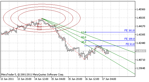
Fig. 2. Some graphical object for analysis: an ellipse, the Fibonacci Fan, the Fibonacci Expansion
There are over forty graphical objects in the MetaTrader 5 client terminal in total. All those objects can be used separately, but more often they're used in a chain of interconnected objects. For example, when an edit field (OBJ_EDIT) is used, a bitmap label (OBJ_LABEL) is used together with it very often to indicate the function of the edit field.
When using an edit field, you often have to check the correctness of data input by a user as well as to provide the possibility of using both a dot and a comma as a decimal separator.
When using a programmatic output of data, you should format the data. For example, you should delete unnecessary zeros. Thus, it would be easier to have a single object that includes the edit field, the bitmap label and some other functional features.
Currently , there is a certain set of graphical controls in the world of programming, which is used in almost every application: a form (the base of an application interface, where all the control elements are located), a frame (it allows grouping and separating sets of elements that have one functional purpose), a button, an edit field, a label, a check box, radio buttons, vertical and horizontal scrollbars, a list, a drop down list, a menu row, a menu tab (fig. 3).
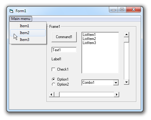
Fig. 3. The form with most common standard controls
The way the elements mentioned above are represented in MQL5 is similar to other programming languages (a button and an edit field). It would be convenient to have other widespread controls in your arsenal.
Several development environments provide programmers with special tools for creation of custom controls. MQL5 doesn't provide such feature. However, since MQL5 is an object-oriented language, it's not necessary to have it. Everything can be done in the form of separate programmed objects.
The principles and the methodology of creation of custom controls will be discussed further in this article. On their basis, everyone who is skilled in programming can create a required set of controls that can be repeatedly used in applications.
1. What Should Be a Graphical Control
1.1. General Requirements and Principles
To be useful, the graphical controls should make the development of applications easier. To be so, they should satisfy the following requirements:
- It should be possible to quickly create a control during development. This problem is solved using the object-oriented approach to programming. One graphical control is represented as one programmed object.
- A control should be flexible. In other words, it should be possible to change its properties: size, position, color, etc.
- A control should be easy to use - it should have only required properties and methods, whose purpose is understandable from the element's purpose and names of the methods. Now let's divide the properties of controls into categories:
- Uncontrolled properties. Such properties include the color scheme. All controls that are used in an application should have a general style. That's why setting of colors for each control individually would be exhausting.
In addition, searching for a color for some controls is a pretty hard task that I don't want to waste time for. For example, a scroll bar. Some web developers may have faced this interesting task.
- Properties set at the stage of creation of a control or rarely changed properties. For example, the size of a control. Balanced and convenient position of all controls used in an application is a special and a hard task that is solved on the stage of making the interface.
In connection with it, the size of controls is usually not change during the program operation. However, sometimes you might need to change such properties. That's why you should provide the possibility to change these properties during operation of the program.
- Main operational properties. Properties that are frequently change from the program. The properties that form the purpose of a control. These properties can be divided into two categories:
- Properties with automatic updating of displaying of a control. For example, an edit. Once a value is set by the program, the changes should be displayed on the screen. In programming, it should be performed using a single line of code.
- Properties that require a compulsory refreshing of displaying. For example, a list. Lists imply working with data arrays, that's why a list should not be refreshed after working with a single element of the list. Here, it's better to perform a compulsory updating at the end working with all elements of the list. This approach increases the application performance significantly.
- A possibility of quick and simple hiding and showing of the control. Making a control visible should not require repeated setting of the displaying properties; the access to object properties should be independent of visibility of the graphical objects of this control. In other words, a programmed object should contain all properties of the control in it and shouldn't use the properties of the graphical objects.
- In order to have output of events that correspond to the control, there should be processing of events of individual graphical objects that are included in the control.
1.2. The Way of Using a Control and Required Methods
Considering the requirements mentioned above, we have the following scheme of creation of a graphical interface as well as the set of required properties and methods of a programmed object:
- Initialization of a control and parallel setting of rarely changed properties. This method will be called Init(); it has several parameters. The 1-st obligatory one - the name of a control. This parameter will be used as a prefix for the names of all graphical objects included in the control. In addition, the parameters that set the size of the control and other parameters can be included (depending on the purpose of the control).
- Controls can have a fixed location on a chart as well as their may require a possibility to be moved. Thus we're going to use separate methods for determining of coordinates: SetPosLeft() - setting the X coordinate, SetPosTop() - setting the Y coordinate. Each of these methods should have one parameter. Very often it's necessary to change both coordinates, so it's good to have the SetPos() method with two parameters, which changes both the X and Y coordinates simultaneously.
To calculate the location of a control, you might need to get the information about the size and location of another control. For this purpose, we're going to use the following methods: Width() - width, Height() - height, Left() - the X coordinate, Top() - the Y coordinate. At this stage of operation, the coordinates of the control are calculated and methods of setting them are called.
- Right after creation or at another stage of operation of the application, we need to make the control visible. To do it, the Show() method is used. To hide the control, the Hide() method is used.
- As was mentioned before, during operation of the program we might need to change the size of the control. That's why the programmed object should have separate methods for setting the size - SetWidth() and/or SetHeght(). Since those are rarely changed properties, for changes to take effect we need to call the Refresh() method, which updates the displaying.
- The events of individual graphical objects will be processed in the Event() method, which will return a value that corresponds to a specific event of the control. The Event() method should be called from the OnChartEvent() function; it will have the same set of parameters as the OnChartEvent() function.
Thus we get the set of required methods of a programmed object:
- void Init(string aName...) - initialization of the control;
- void SetPosLeft(int aLeft) - setting of the X coordinate;
- void SetPosTop(int aTop) - setting of the Y coordinate;
- void SetPos(int aLeft, int aTop) - simultaneous setting of the X and Y coordinates;
- void SetWidth(int aWidth) - setting of the width;
- void SetHeght(int aHeight) - setting of the height;
- int Width() - getting the width;
- int Height() - getting the height;
- int Left() - getting the X coordinate;
- int Top() - getting the Y coordinate;
- void Refresh() - full refreshing of displaying;
- void Show() - showing;
- void Hide() - hiding;
- int Event(const int id, const long & lparam, const double & dparam, const string & sparam) - processing of chart events;
Presence of the other methods (or absence of some of the listed methods) depends on the control itself and on its purpose.
Later in this article we are going to try to implement the principles described above - we are going to create a control for a user to enter a text or a number.
Before it, we need to provide ourselves with the tools for quick and convenient working with graphical objects.
2. How to Work with Graphical Objects Quickly and Conveniently
For working with graphical objects, MQL5 provides the following basic functions: ObjectCreate(), ObjectDelete(), ObjectSetDouble(), ObjectSetInteger(), ObjectSetString(), ObjectGetDouble(), ObjectGetInteger(), ObjectGetString(). We can use those functions directly, but the process of programming will be very laborious and long. The functions have long names; a lot of identifiers that have long names must be passed to the functions.
To make the work with graphical objects more convenient, we can use a ready-made class that is included in the MetaTrader 5 client terminal package (the CChartObject class from the MQL5/Include/ChartObjects/ChartObject.mqh file), or we can write our own class and give it all the necessary methods.
Jokingly, this approach to programming consists of pressing one key with a dot after. After specifying the name of an object it is left to put a dot and the list of its properties and methods is open; just choose a necessary item from the list (fig. 4).
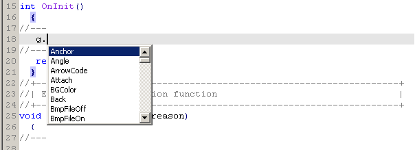
Fig. 4. The list of properties and methods of the object
There are two variants of managing a graphical object using the auxiliary class:
- An individual class instance is created for each graphical object. Pretty convenient but not economical method from the amount of consumed memory point of view. For this variant, it's better to write special classes for each type of graphical object. But this approach is not optimal since it is very laborious. In distinct from programming of Expert Advisors, there is no strict requirement on maximum performance when creating a user interface.
- Use one class instance. If it is necessary to manage a graphical object, the object is added to the class. We're going to use the second variant.
Let's create a universal class that is most suitable for the second type of managing the graphical objects.
3. The Universal Class for Managing the Graphical Objects
During programming, the work with each graphical object consists of three stages: creation, reading/setting properties, deleting at the end of operation of the application.
So first of all, the class for managing the graphical objects should contain the methods that create them. An obligatory parameter for creation of a graphical object is its name; thus the methods of creation of objects will have one obligatory parameter for specifying a name of a created object.
Usually, graphical objects are created on the chart, where the program (Expert Advisor, Indicator or Script) is run. A more rare case is a subwindow, and an even rarer case is another chart window of the terminal. Thus the second optional parameter will be the one that specifies the number of a subwindow; and the third one is the identifier of a chart.
On default, both optional parameters will be equal to 0 (price chart is on its "own" chart). Look up the list of types of graphical objects in the documentation. Add the Create method for each type.
Before it, we need to create a file. To do it, open MetaEditor, create a new include file and call it IncGUI.mqh. In the open file, create the CGraphicObjectShell class with the protected and public sections. In the protected section, declare variables for the name of an object and the identifier of a chart.
In the methods of creation of objects, those variables will be assigned the values passed by methods as parameters, in order to have a possibility to manage them after creation of object without specifying a name and a chart identifier. Thus we can also use the class for the first variant of managing the graphical objects.
To have a possibility of using the class for the second variant (to manage any graphical object), give it a method of attaching a graphical object (the Attach() method). This method will have one obligatory parameter - the name of a graphical object, and one optional parameter - a chart identifier. May be you'll need to know the name and the identifier of an attached graphical object. To do it, add the following methods to the object: Name() and ChartID().
As a result, we get the following "workpiece" of the class:
class CGraphicObjectShell
  {
protected:
   string            m_name;
   long              m_id;
public:
   void Attach(string aName,long aChartID=0)
     {
      m_name=aName;
      m_id=aChartID;
     }
   string Name()
     {
      return(m_name);
     }
   long ChartID()
     {
      return(m_id);
     }
  };
Add the above mentioned methods of creation of graphical objects. Names of those methods will start with "Create".
Readers can skip it, the file IncGUI.mqh attached to the article contains the ready-made class CGraphicObjectShell.
As an example, here is one method of creation of the vertical line graphical object (OBJ_VLINE):
void CreateVLine(string aName,int aSubWindow=0,long aChartID=0)
  {
   ObjectCreate(m_id,m_name,OBJ_VLINE,aSubWindow,0,0);
   Attach(aName,aChartID);
  }
Now open the list of properties of graphical objects in the user guide; and write methods of setting a value for each property using the ObjectSetDouble(), ObjectSetInteger() and ObjectSetString() functions. Name of the methods will start with "Set". Next, write methods for reading the properties using the ObjectGetDouble() and ObjectGetInteger() functions. ObjectGetString().
As an example, here are methods for setting and getting the color:
void SetColor(color aColor)
  {
   ObjectSetInteger(m_id,m_name,OBJPROP_COLOR,aColor);
  }
color Color()
  {
   return(ObjectGetInteger(m_id,m_name,OBJPROP_COLOR));
  }
Well, now we seem to have the minimum required tools for working with graphical objects, but not all of them.
Sometimes when working with a graphical object, you may need to perform only one action with an object. In this case, it won't be convenient to execute the Attach() method for the object, and then return to the main object and execute Attach() for it again.
Let's add two more variants of all methods of setting/getting of properties to the class.
The first one - by name on its "own" chart:
void SetColor(string aName,color aColor)
  {
   ObjectSetInteger(0,aName,OBJPROP_COLOR,aColor);
  }
color Color(string aName)
  {
   return(ObjectGetInteger(0,aName,OBJPROP_COLOR));
  }
The second one - by name and identifier of a chart:
void SetColor(long aChartID,string aName,color aColor)
  {
   ObjectSetInteger(aChartID,aName,OBJPROP_COLOR,aColor);
  }
color Color(long aChartID,string aName)
  {
   return(ObjectGetInteger(aChartID,aName,OBJPROP_COLOR));
  }
In addition to the ObjectGet... and ObjectSet... functions, there are other functions for working with graphical objects: ObjectDelete(), ObjectMove(), ObjectFind(), ObjectGetTimeByValue(), ObjectGetValueByTime(), ObjectsTotal(). They can also be added to the class with three variants of calling of each one.
Finally, declare the CGraphicObjectShell class with a simple and short name "g" in this file.
CGraphicObjectShell g;
Now, to start working with graphical objects, it's sufficient to connect the IncGUI.mqh file; thus we will have the "g" class to work with. Using it, it's easy to manage all the available graphical objects.
4. Workpieces for Controls
Despite we have the class for quick working with graphical objects, we can create controls in an easier way. All controls can be created on the basis of four graphical objects:
- Rectangle label (OBJ_RECTANGLE_LABEL),
- Text label (OBJ_LABEL),
- Edit field (OBJ_EDIT),
- Button (OBJ_BUTTON).
After creation of graphical objects, a lot of properties should be set for them: coordinates, size, color, font size, etc. To hasten the process, let's create another class and name it CWorkPiece (workpieces), and supply it with methods for creation of graphical objects with properties passed in parameters.
For the controls to work, you need to handle the chart events. Events of the other charts are not available, thus we are going to work only with the own chart - there will be no chart identifier in the parameters of methods of the CWorkPiece class. 0 (own chart) will be used everywhere.
The parameter that specifies a subwindow number will be used to provide the possibility of creation of controls both in the price chart and in its subwindows. The graphical objects will be bound only to the upper left corner; if it's necessary to relocate a control relatively to any other corner, it is much easier to recalculate the coordinates of the entire control considering the chart size. To control the changes of size of the chart, you can handle the CHARTEVENT_CHART_CHANGE event.
As a base for many controls, we are going to use the "Rectangle label" object; add the method of creation of this object to the CWorkPiece class; the method is called Canvas():
void Canvas(string aName="Canvas",
             int aSubWindow=0,
             int aLeft=100,
             int aTop=100,
             int aWidth=300,
             int aHeight=150,
             color aColorBg=clrIvory,
             int aColorBorder=clrDimGray)
  {
   g.CreateRectangleLabel(aName,aSubWindow); // Creation of rectangle label
   g.SetXDistance(aLeft);                    // Setting of the X coordinate
   g.SetYDistanse(aTop);                        // Setting of the Y coordinate
   g.SetXSize(aWidth);                          // Setting of width
   g.SetYSize(aHeight);                         // Setting of height
   g.SetBgColor(aColorBg);                   // Setting of background color
   g.SetColor(aColorBorder);                 // Setting of border color
   g.SetCorner(CORNER_LEFT_UPPER);             // Setting of a anchor point
   g.SetBorderType(BORDER_FLAT);             // Setting of border type
   g.SetTimeFrames(OBJ_ALL_PERIODS);            // Setting visibility at all timeframes
   g.SetSelected(false);                        // Disabling selection
   g.SetSelectable(false);                   // Disabling of selection possibility
   g.SetWidth(1);                               // Setting of border width
   g.SetStyle(STYLE_SOLID);                  // Setting of border style
  }
Pay attention: the method consists of 14 lines of code; it would be very frustrating to write all of them each time you create this object. Now it's sufficient to write only one line, all parameters of the method are optional and are listed in the order of frequency of their use: position, size, color, etc.
Similarly to the Canvas() method, write the methods of creation of a text label, a button and an edit field: Label(), Button() and Edit(). The ready-made class CWorkPiece is attached to the article in the IncGUI.mqh file. In addition to the methods mentioned above, the class contains several other methods: Frame() and DeleteFrame() - the methods of creation and deletion of a frame (fig. 5). A frame is a rectangle label with a caption in the upper left corner.
The frames are planned to be used when grouping controls in a form.
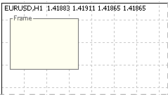
Fig. 5. The frame with caption.
The list of all methods of the CWorkPiece class is attached to the article.
Similarly to CGraphicObjectShell class, declare the CWorkPiece class with the short name "w" to be able to use it right after connecting the IncGUI.mqh file.
CWorkPiece w;
All the auxiliary tools are ready, so we can continue with the subject of the article - creation of a custom control.
5. Creation of an "Edit" Control
First of all, not to confuse the terminology, let's call the graphical object OBJ_EDIT as a text field, the OBJ_LABEL object - as a label, and the created controls - as an edit field. The created control consists of two graphical objects: an edit field (OBJ_EDIT) and a text label (OBJ_LABEL).
Te control will support two modes of operation: input of text data and input of numeric data. In the mode of input of numeric data, there will be a limitation on the range of input values and both a comma and a dot will be acceptable as decimal separators. At a programmed output of a value in the edit field, it is formatted according to a specified number of decimal places.
Thus, when initializing a control, we should specify its mode of operation: text or numeric; the mode is specified using the aDigits parameter. A value that is greater than zero sets the numeric mode with the specified number of decimal places, a negative value set the text mode.
On default, the range of acceptable values is from -DBL_MAX to DBL_MAX (the entire range of values of a double variable). If necessary, you can set another range by calling the SetMin() and SetMax() methods. Among the size parameters, only width will be set for the control. For the edit field to look balanced, a corresponding height and width should be set for it.
A change of font size requires the corresponding change of height of the graphical object. And that requires changing location of all the other controls; no one would do this. We suppose the use of a constant font size for all controls and the corresponding edit fields. However, the class of the control will have a method that returns its height for convenience of calculation of coordinates of other elements.
There will be four color parameters: background color, text color, caption color and warning color (it will be possible to change the background color of the text field to draw a user's attention, for example, in case of inputting an incorrect value).
As was mentioned before, controls in a subwindow are supported. In addition to main parameters that are required for a control to work, we are going to use the other parameter Tag; it is a simple text value that is stored in an instance of the class. A tag is a convenient auxiliary tool.
The class will be called CInputBox. So, we have the following set of variables of the class (located in the private section):
string m_NameEdit;    // Name of the Edit object
string m_NameLabel;   // Name of the Label object
int m_Left;           // X coordinate
int m_Top;            // Y coordinate
int m_Width;           // Width
int m_Height;          // Height
bool m_Visible;        // Visibility flag of the control
int m_Digits;          // Number of decimal places for the double number; -1 set the text mode
string m_Caption;      // Caption
string m_Value;        // Value
double m_ValueMin;     // Minimum value
double m_ValueMax;     // Maximum value
color m_BgColor;       // Background color
color m_TxtColor;     // Text color
color m_LblColor;      // Caption color
color m_WarningColor; // Warning font color
bool m_Warning;        // Flag of warning
int m_SubWindow;       // Subwindow
string m_Tag;           // Tag
When using a control, the first method that is called is Init().
In this method, we prepare the values of all parameters determined before:
// The initialization method
void Init(string aName="CInputBox",
           int aWidth=50,
           int aDigits=-1,
           string aCaption="CInputBox")
 {
   m_NameEdit=aName+"_E";  // Preparing the name of the text field
   m_NameLabel=aName+"_L"; // Preparing the caption name
   m_Left=0;                 // X coordinate
   m_Top=0;                  // Y coordinate
   m_Width=aWidth;          // Width
   m_Height=15;             // Height
   m_Visible=false;         // Visibility
   m_Digits=aDigits;       // The mode of operation and the number of decimal places
   m_Caption=aCaption;     // Caption text
   m_Value="";              // Value in the text mode
   if(aDigits>=0)m_Value=DoubleToString(0,m_Digits); // Value in the numeric mode
   m_ValueMin=-DBL_MAX;                   // Minimal value
   m_ValueMax=DBL_MAX;                  // Maximal value
   m_BgColor=ClrScheme.Color(0);       // Background color of the text field
   m_TxtColor=ClrScheme.Color(1);      // Color of text and frame of the text field
   m_LblColor=ClrScheme.Color(2);      // Caption color
   m_WarningColor=ClrScheme.Color(3); // Warning color
   m_Warning=false;                      // Mode: warning, normal
   m_SubWindow=0; // Number of subwindow
   m_Tag=""; // Tag
 }
If a control works in the text mode, the m_Value variable is assigned the value "", if it works in the numeric mode - a zero with the specified number of decimal places. The color parameters are set to their defaults; we will deal with the color schemes at the last stage.
Variables that determine the coordinates of the control are set to zeros, because the control is not visible yet. After calling the Init() method (if it is planned that the control will have a fixed position on the chart) we can set coordinates using the SetPos() method:
// Setting the X and Y coordinates
void SetPos(int aLeft,int aTop)
{
   m_Left=aLeft;
   m_Top=aTop;
}
After it, we can make the control visible (the Show() method):
// Enable visibility on the previously specified position
void Show()
{
   m_Visible=true; // Registration of visibility
   Create();       // Creation of graphical objects
   ChartRedraw();   // Refreshing of the chart
}
The Create() function is called from the Show() method; it creates graphical objects (located in the private section), then the chart is refreshed (ChartRedraw()). The code of the Create() function is given below:
// The function of creation of graphical objects
void Create(){
   color m_ctmp=m_BgColor;  // Normal background color
      if(m_Warning){ // The warning method is set
         m_ctmp=m_WarningColor; // The text field will be color in the warning color
      }
    // Creation of the text field
   w.Edit(m_NameEdit,m_SubWindow,m_Left,m_Top,m_Width,m_Height,m_Value,m_ctmp,m_TxtColor,7,"Arial");
      if(m_Caption!=""){ // There is a caption
          // Creation of caption
         w.Label(m_NameLabel,m_SubWindow,m_Left+m_Width+1,m_Top+2,m_Caption,m_LblColor,7,"Arial");
      }
}
When creating graphical objects in the Create() function depending on the value of the m_Warning, the text field is assigned the corresponding color of background. If the m_Caption variable has a value, the caption is created (you can create a control without caption).
If you plan to make a movable control, use the second variant of the Show() method - with specifying of coordinates. In this method, the coordinates are set and the first variant of the Show() method is called:
// Setting the X and Y coordinates
void SetPos(int aLeft,int aTop){
   m_Left=aLeft;
   m_Top=aTop;
}
After the control is displayed, you will need to hide it some time.
The Hide() method is used for this purpose:
// Hiding (deletion of graphical objects)
void Hide()
{
   m_Visible=false; // Registration of the invisible state
   Delete();        // Deletion of graphical objects
   ChartRedraw();    // Refreshing of the chart
}
The Hide() method calls the Delete() function that deletes graphical objects, and then it calls the ChartRedraw() function to refresh the chart. The Delete() function is in the private section:
// The function of deletion of graphical objects
void Delete()
{
   ObjectDelete(0,m_NameEdit);  // Deletion of the text field
   ObjectDelete(0,m_NameLabel); // Deletion of caption
}
Since we've already met a method that only sets the values of properties without changing the displaying of a control (the SetPos() method), it is logical to create a method for a forced refreshing of a control - the Refresh() method:
// Refreshing of displaying (deletion and creation)
void Refresh()
{
   if(m_Visible)
   {   // Visibility enabled
      Delete();     // Deletion of graphical object
      Create();     // Creation of graphical objects
      ChartRedraw(); // Redrawing of the chart
   }
}
The control is pretty simple, that is why we use the simple method of refreshing - deletion and creation. If it were a more complex control like a list that consists of many edit fields, then we would choose a smarter approach.
So, we are done with placing of the control. Now let's proceed with setting a value - the SetValue() method. Since the control can work in two modes, there will be two variants of the SetValue() method: with the string and double type. In the text mode, the value is used as is:
// Setting a text value
void SetValue(string aValue)
{
   m_Value=aValue; // Assigning a value to variable to store it
      if(m_Visible)
      { // The visibility of the control is enabled
          // Assigning the text field to the object for managing graphical objects
         g.Attach(m_NameEdit);
         g.SetText(m_Value); // Setting the value for the text field
         ChartRedraw();        // Redrawing the chart
      }
}
The obtained argument is assigned to the m_Value variable, and if the control is visible, it is displayed in the text field.
In the numeric mode, the obtained argument is normalized according to the m_Digits value, then it is corrected according to the maximal and minimal value (m_MaxValue, m_MinValue), transformed in a string, and then the first method SetValue() is called.
// Setting a number value
void SetValue(double aValue)
{
   if(m_Digits>=0)
   {  // In the numeric mode
       // Normalization of the number according to the specified accuracy
      aValue=NormalizeDouble(aValue,m_Digits);
      // "Alignment" of the value according to the minimal acceptable value
      aValue=MathMax(aValue,m_ValueMin);
       // "Alignment" of the value according to the maximal acceptable value
      aValue=MathMin(aValue,m_ValueMax);
       // Setting the obtained value as a string
      SetValue(DoubleToString(aValue,m_Digits));
   }
   else
   { // In the text mode
      SetValue((string)aValue); // Assigning the value to the variable to store it as is
   }
}
Let's write two methods for getting values: one is for getting a string value, the other is for getting a double value:
// Getting a text value
string ValueStrind()
{
   return(m_Value);
}

// Getting a numeric value
double ValueDouble()
{
   return(StringToDouble(m_Value));
}
The value that is set for the control is corrected according to the maximal and minimal acceptable values; let's add methods for getting and setting them:
// Setting the maximal acceptable value
void SetMaxValue(double aValue)
{
   m_ValueMax=aValue; // Registration of the new maximal accepted value
      if(m_Digits>=0)
     { // The control works in the numeric mode
         if(StringToDouble(m_Value)>m_ValueMax)
         { /* The current value of the control is greater than the new maximal acceptable value*/
            SetValue(m_ValueMax); // Setting the new value that is equal to the maximal accepted value
         }
      }
}

// Setting the minimal acceptable value
void SetMinValue(double aValue)
{
   m_ValueMin=aValue; // Registration of the new minimal acceptable value
      if(m_Digits>=0)
      { // The control works in the numeric mode
         if(StringToDouble(m_Value)<m_ValueMin)
         { /* The current value of the control is less than the new minimal acceptable value*/
            SetValue(m_ValueMin); // Setting the new value that is equal to the minimum acceptable value
         }
      }
}

// Getting the maximal accepted value
double MaxValue()
{
   return(m_ValueMax);
}

// Getting the minimal accepted value
double MinValue()
{
   return(m_ValueMin);
}
If the control works in the numeric mode, the check and correction (if necessary) of the current value is performed when setting new maximum and minimum acceptable values.
Now let's deal with input of a value by a user, the Event() method. The check of data input by a user will be performed using the CHARTEVENT_OBJECT_ENDEDIT event. When working in the text mode, if a value specified by a user is not equal to m_Value, then the new value is assigned to m_Value as well as the value 1 is assigned to the m_event variable returned from the Event() method.
When working in the numeric mode, memorize the previous value of m_Value in the m_OldValue variable, replace the comma with a dot, convert the string into number and pass it to the SetValue() function. Then if m_Value and m_OldValue are not equal, "generate" the event (set the value 1 to the m_event variable).
// Handling of events
int Event(const int id,
           const long & lparam,
           const double & dparam,
           const string & sparam)
{
   bool m_event=0; // Variable for an event of this control
      if(id==CHARTEVENT_OBJECT_ENDEDIT)
      { // There has been an event of end of editing the text field
         if(sparam==m_NameEdit)
         { // The text field with the name m_NameEdit has been modified
            if(m_Digits<0)
            { // In the text mode
               g.Attach(m_NameEdit); // Assigning the text field for controlling it
                  if(g.Text()!=m_Value)
                  { // New value in the text field
                     m_Value=g.Text(); // Assigning the value to the variable to store it
                     m_event=1;         // There has been an event
                  }
            }
            else
            { // In the numeric mode
               string m_OldValue=m_Value; // The variable with the previous value of the control
               g.Attach(m_NameEdit);      // Attaching the text field for controlling it
               string m_stmp=g.Text();     // Getting text specified by a user in the text field
               StringReplace(m_stmp,",",".");       // Replacing comma with a dot
               double m_dtmp=StringToDouble(m_stmp); // Conversion to a number
               SetValue(m_dtmp);                     // Setting the new numeric value
                     // Comparing the new value with the previous one
                  if(StringToDouble(m_Value)!=StringToDouble(m_OldValue))
                  {
                     m_event=1; // There has been an event
                  }
            }
         }
      }
   return(m_event); // Return the event. 0 - there is no event, 1 - there is an event
}
Support of working of the control in subwindows. To provide it, add the SetSubWindow() method that should be called from the OnChartEvent() function in case of a CHARTEVENT_CHART_CHANGE event. If you plan to use the control only on a price chart, there is no need to call this method.
The m_SubWindow variable is already declared, it is equal to 0 on default and it is passed to the Edit() and Label() methods of the "w" class at creation of graphical objects of a control. The number of a subwindow will be passed to the SetSubWindowName() method; if the number is changed, change the value of the m_SubWindow variable and execute the Refresh() method.
// Setting a subwindow by number
void SetSubWindow(int aNumber)
{
   int m_itmp=(int)MathMax(aNumber,0); /* If the number is negative, 0 will be used - the price chart*/
      if(m_itmp!=m_SubWindow)
      { /* The specified number doesn't correspond the number where the control is located*/
         m_SubWindow=m_itmp; // Registration of the new number of subwindow
         Refresh(); // Recreation of the graphical objects
      }
}
Probably, it will be more convenient to pass the name of a subwindow instead of its number to the function. Add another variant of the SetSubWindow() method:
// Setting a subwindow by name
void SetSubWindow(string aName)
{
   SetSubWindow(ChartWindowFind(0,aName)); // Determination of the number of the subwindow by its name and setting the subwindow by number
}
Supply the class of the control with the other missing methods, according to the concept stated at the beginning of the article.
As soon as we have the SetPos() method that allows setting both coordinates of the control simultaneously, add the methods for separate setting of coordinates:
// Setting the X coordinate
void SetPosLeft(int aLeft)
{
   m_Left=aLeft;
}

// Setting the Y coordinate
void SetPosTop(int aTop)
{
   m_Top=aTop;
}
Method of setting a width:
// Setting the width
void SetWidth(int aWidth)
{
   m_Width=aWidth;
}
Method of getting the coordinates and the size:
// Getting the X coordinate
int Left()
{
   return(m_Left);
}

// Getting the Y coordinate
int Top()
{
   return(m_Top);
}

// Getting the width
int Width()
{
   return(m_Width);
}

// Getting the height
int Height()
{
   return(m_Height);
}
The methods for working with the tag:
// Setting the tag
void SetTag(string aValue)
{
   m_Tag=aValue;
}

// Getting the tag
string Tag()
{
   return(m_Tag);
}
The methods for warning:
// Setting the warning mode
void SetWarning(bool aValue)
{
      if(m_Visible)
      { // Visibility is enabled
         if(aValue)
         { // We need to turn on the warning mode
            if(!m_Warning)
            { // The warning mode has not been enabled
               g.Attach(m_NameEdit);         // Attaching the text field for controlling
               g.SetBgColor(m_WarningColor); // Setting the warning color of text in the text field
            }
         }
         else
         { // We need to disable the warning mode
            if(m_Warning)
            { // The warning mode is enabled
               g.Attach(m_NameEdit);    // Attach the text field for controlling
               g.SetBgColor(m_BgColor); // Setting the normal font color
            }
         }
      }
   m_Warning=aValue; // Registration of the current mode
}

// Getting the warning mode
bool Warning()
{
   return(m_Warning);
}
If the control is visible when setting the warning mode, the value of the parameter passed to the SetWarning method is checked; if its value does not correspond to the current state of the control, the background color of the text field is changed.
Anyway the set mode is registered, not to set the corresponding color to the text field in case the control is invisible.
There is one property left - m_Digits. Let's add methods for getting and setting its value:
// Setting the number of decimal places
void SetDigits(int aValue)
{
   m_Digits=aValue; // Registration of the new value
      if(m_Digits>=0)
      { // The numeric mode
         SetValue(ValueDouble()); // Resetting of the current value
      }
}

// Getting the m_Digits value
int Digits()
{
   return(m_Digits);
}
Well, we are done with the most interesting part. Now it's time for the most beautiful.
6. Color Schemes
Color schemes will be stored in the variables of the CСolorSchemes class.
The class will be declared beforehand in the IncGUI.mqh file with the name ClrScheme. To set a color scheme, we will call the SetScheme() method with the number of a color scheme specified as a parameter. If the SetScheme() method is not called, the color scheme with the number 0 will be used.
To get a color, we will use the Color() method with a specified number of color from the color scheme. Let's write the CСolor Schemes class with the private and public sections. In the private section, declare the m_ShemeIndex variable for storing the index of a color scheme. In the public section, write the SetScheme() method:
// Setting the color scheme number
void SetScheme(int aShemeIndex)
{
   m_ShemeIndex=aShemeIndex;
}
The Color() method. A two-dimensional array is declared in the method: the first dimension is the color scheme number; the second one is the color number in the scheme. Depending on the specified number of a color scheme, it returns the color by number specified in the method parameters.
color Color(int aColorIndex)
{
   color m_Color[3][4];  // The first dimension - the color scheme number, the second one - the number of the color in the color scheme
   // default
   m_Color[0][0]=clrSnow;
   m_Color[0][1]=clrDimGray;
   m_Color[0][2]=clrDimGray;
   m_Color[0][3]=clrPink;
   // yellow-black
   m_Color[1][0]=clrLightYellow;
   m_Color[1][1]=clrBrown;
   m_Color[1][2]=clrBrown;
   m_Color[1][3]=clrPink;
   // blue
   m_Color[2][0]=clrAliceBlue;
   m_Color[2][1]=clrNavy;
   m_Color[2][2]=clrNavy;
   m_Color[2][3]=clrPink;
   return(m_Color[m_ShemeIndex][aColorIndex]); // Returning a value according to the scheme number and the number of color in the scheme
}
For now, the color schemes include four colors each; at that two of them have the same values. Further, when creating other controls, we may need more colors.
To easily find an appropriate color in the scheme or decide on adding a new color, the class includes a method that allows viewing the colors - the Show() method (fig. 6). And also there is the reverse method Hide() for deleting color examples from the chart.
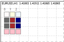
Fig. 6. Viewing color schemes using the Show() method
The article has the ColorSchemesView.mq5 attached. It is an Expert Advisor for viewing color schemes (ColorSchemesView.mq5).
Let's modify the Init() method in the CInputBox class slightly. Replace its colors with the colors from the ClrScheme class:
m_BgColor=ClrScheme.Color(0);       // Background color of the text field
m_TxtColor=ClrScheme.Color(1);      // Font color and frame color of the text field
m_LblColor=ClrScheme.Color(2);     // Caption color
m_WarningColor=ClrScheme.Color(3); // Warning color
This is the end of creation of one control; and now we have the base for developing any other controls.
7. Using the Control
Let's create and Expert Advisor and name it GUITest; connect the IncGUI.mqh file:
#include <IncGUI.mqh>Declare the CInputBox class with the name ib:CInputBox ib;
In the OnInit() of the EA, call the Init() method of the ib object:
ib.Init("InpytBox",50,4,"input");
Make the control visible and set a position for it:
ib.Show(10,20);
In the OnDeinit() function of the EA, delete the control:
ib.Hide();
Compile and attach the Expert Advisor to a chart. You'll see our control (fig. 7).
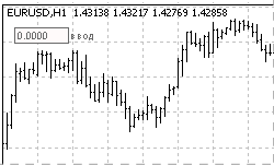
Fig. 7. The InputBox Control
Add the possibility of changing the color scheme to the Expert Advisor.
At this moment, we have three color schemes. Let's make a enumeration and an external variable for choosing a color scheme:
enum eColorScheme
  {
   DefaultScheme=0,
   YellowBrownScheme=1,
   BlueScheme=2
  };

input eColorScheme ColorScheme=DefaultScheme;
At the very beginning of the OnInit() function of the Expert Advisor, add setting of a color scheme:
ClrScheme.SetScheme(ColorScheme);
Now in the window of properties of the EA we can choose one of three color schemes (fig. 8).
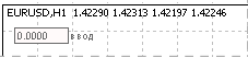
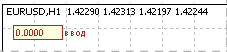
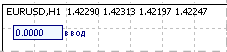
Fig. 8. Different Color Schemes
To handle the event of specifying a new value, add the following code to the OnChartEvent() function of the EA:
if(ib.Event(id,lparam,dparam,sparam)==1)
  {
   Alert("Entered value "+ib.ValueStrind());
  }
Now, when a new value is specified in the edit field, a message window informing about the specified value is opened.
Supply the Expert Advisor with the possibility of creation of controls in a subwindow.
Firstly, create a test indicator TestSubWindow (attached in the TestSubWindow.mq5 file). When creating the indicator in the MQL5 Wizard, specify that it should work in a separate subwindow. Add the following code to the OnChartEvent() function of the EA:
if(CHARTEVENT_CHART_CHANGE)
  {
   ip.SetSubWindow("TestSubWindow");
  }
Now, if the indicator is not on the chart, the control is created on the price chart. If you attach the indicator to the chart, the control will jump to the subwindow (fig. 9). If you delete the indicator, the control will return back to the price chart.
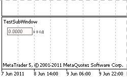
Fig. 9. The control in the subwindow
Conclusion
As a result of work done, we have the IncGUI.mqh include file that contains the following classes: CGraphicObjectShell (creation and management of graphical objects), CWorkPiece (fast creation of several graphical objects with setting their properties using parameters), CColorSchemes (setting a color scheme and getting color of the current color scheme) and one class of a control - CInputBox.
The CGraphicObjectShell, CWorkPiece and CColorSchemes class are already declared in the file with the names "g", "w" and "ClrScheme", i.e. they are ready to use right after connecting the IncGUI.mqh file.
Let's repeat how to use CInputBox class:
- Connect the IncGUI.mqh file.
- Declare a class of the CInputBox type.
- Call the Init() method.
- Set coordinates using the SetPos() method; turn on the visibility using Show() if necessary. The second variant: turn on visibility using Show() with specification of coordinates.
- If necessary or at the end of work of the Expert Advisor, hide the control using the Hide() method.
- Add the call of the Event() method to the OnChartEvent() function.
- If you need to create a control in a subwindow, supply the OnChartEvent() function with a call of the SetSubWindow() method when a CHARTEVENT_CHART_CHANGE event occurs.
- To use color schemes, call the SetScheme() method of the ClrScheme class before calling the Init() method.
Attachments
- IncGUI.mqh - main include file. The file should be placed in the MQL5/Include folder of the client terminal data folder.
- GUITest.mq5 - the Expert Advisor with an example of the CInputBox control. The file should be placed in the MQL5/Experts folder of the client terminal data folder.
- TestSubWindow.mq5 - the indicator for testing the function for displaying of a control in a subwindow. The file should be placed in the MQL5/Indicators folder of the client terminal data folder.
- ColorSchemesView.mq5 - the Expert Advisor for viewing the color schemes. An auxiliary tool for creation of controls. The file should be placed in the MQL5/Experts folder of the client terminal data folder.
- IncGUImqh.chm - documentation for the IncGUI.mqh file.
Translated from Russian by MetaQuotes Ltd.
Original article: https://www.mql5.com/ru/articles/310
Warning: All rights to these materials are reserved by MetaQuotes Ltd. Copying or reprinting of these materials in whole or in part is prohibited.
This article was written by a user of the site and reflects their personal views. MetaQuotes Ltd is not responsible for the accuracy of the information presented, nor for any consequences resulting from the use of the solutions, strategies or recommendations described.

 Interview with Matúš German (ATC 2011)
 Interview with Antonio Morillas (ATC 2011)
 Andrey Bolkonsky (abolk): "Any programmer knows that there is no software without bugs"
- Free trading apps
- Over 8,000 signals for copying
- Economic news for exploring financial markets
You agree to website policy and terms of use
I don't understand the fourth principle. Can you give me an example?
Hi Leo, when you refer to the fourth principle, what exactly are you referring to? I understand that topic 4 of this article concerns "Workpieces for controls". Could you specify your question a little further?
I would like to create a custom graphical object that is a combination of rectangles and boxes and a few bits of information. I will use this object often so ideally I'd like to to be easily accessible. Is it possible to add custom made graphical objects into the MT5 toolbar? If not, could you give some other suggestions please?
Strange...
Isn't that how it's supposed to be
Or like this.
A typo