

MQL5取引ツール(第24回):3Dカーブ、パンモード、ViewCubeナビゲーションによる奥行き感の向上
 91
91
 5
5

はじめに
3D二項分布ビューアに回転やズーム機能が備わっていても、奥行きを正確に表現するカーブ、シーンの注視点を移動する手段、そして視点を素早くリセットする機能がなければ、確率質量関数の形状を確認するには何度も手動で回転操作を繰り返す必要があります。また、中心から外れた領域は見づらく、標準ビューへ戻す際にも手探りでドラッグしなければなりません。本記事は、より高度な確率解析を実現するために、インタラクティブな3D統計ツールへ直感的なナビゲーション機能を追加したいMetaQuotes Language 5 (MQL5)開発者およびアルゴリズムトレーダーを対象としています。
前回の記事(第23回)では、MQL5の二項分布ビューアにDirectX3Dを統合し、2D表示と3D表示を切り替えられる機能に加え、回転・ズーム・自動フィットに対応したカメラ操作を実装しました。第24回となる今回は、さらにツールを強化し、確率質量関数の奥行き感を高めるセグメント化された3Dカーブ、注視点を移動できるパンモード、そしてアニメーション付きのカメラ遷移を備えたViewCubeを実装します。本記事では以下のトピックを扱います。
記事を読み終える頃には、確率分布をより直感的に分析できる高度な3Dナビゲーション機能を備えたMQL5ツールが完成し、用途に応じて自由に拡張できるようになります。それでは始めましょう。
3Dカーブ、パンモード、ViewCubeフレームワークの仕組み
確率質量関数を3D空間内で単なる平面的な投影線として表現すると、3Dレンダリング本来の奥行き表現が失われてしまいます。そこで、隣接するデータ点を結ぶ方向に合わせてボックスプリミティブを配置したセグメント構造のチューブ状カーブを構築することで、カーブそのものに立体感を持たせます。これにより、各ビンの高さの違いを遠近法の中で自然に把握できるようになります。パンモードは別の課題を解決します。回転やズームだけではシーンは固定された注視点を中心に操作されるため、分布が中心から外れていたり試行回数が多かったりすると、注目したい領域が画面端へ寄ってしまいます。カメラ基準のベクトル演算によって注視点そのものを移動させることで、現在の視点角度やズーム倍率を維持したまま、シーン全体を自由に探索できます。ViewCubeは、現在のカメラ回転をリアルタイムに反映するコンパクトな方向表示ウィジェットです。キューブは面・辺・頂点ごとのクリック可能な領域に分割され、それぞれがあらかじめ定義された視点角度へ対応しています。クリックすると視点は瞬時に切り替わるのではなく、補間アニメーションによって滑らかに遷移するため、視覚的にも自然な操作感が得られます。
実際のマーケット分析では、奥行きを持つ3Dカーブとヒストグラムを組み合わせることで、確率質量関数のピークが最頻度ビンと一致しているかを視覚的に確認し、モデルが適切に較正されているかを判断できます。また、パン機能を利用して低確率領域(テール)を画面中央へ移動すれば、極端な結果に基づくポジションサイズの検討前に詳細な分析をおこなえます。さらに、ViewCubeの上面ビューでは全ビンの高さを一度に比較でき、正面ビューでは各ビンの値を読み取りやすくなります。
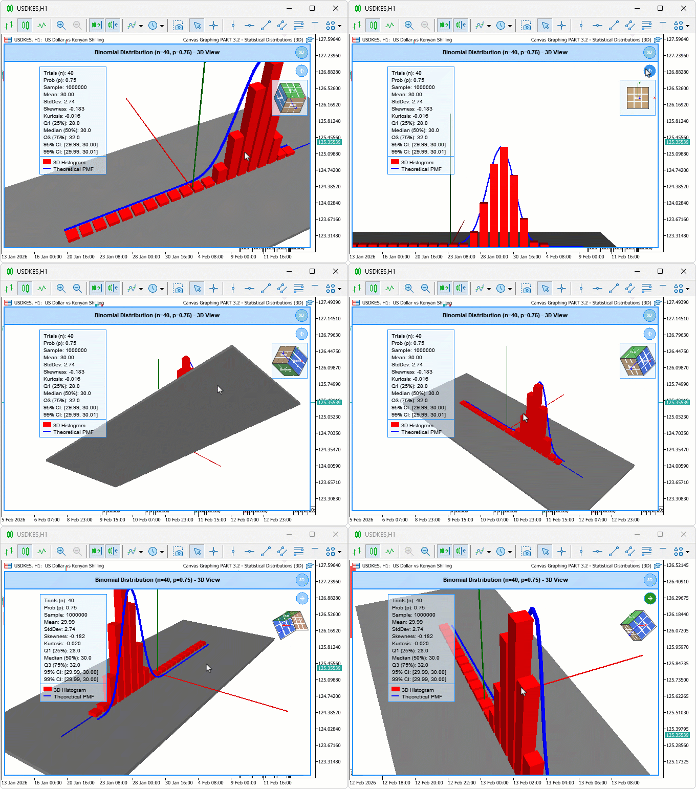
本記事では、ボックスベースのカーブセグメントを生成し、それらを適切なサイズ・回転で配置して連続したチューブ状カーブを構築します。また、カメラ基準のベクトル計算を用いたパン処理、投影頂点と面ソートによる正しい描画順序を備えたViewCubeのレンダリング、さらに細分化されたホバー領域を実現する双線形補間についても実装します。加えて、視点遷移のタイマー制御アニメーション、アイコンやViewCubeを描画するためのアルファブレンドオーバーレイ、クリック・ホバーイベント処理も統合し、ユーザーインターフェース全体をより応答性の高いものへ仕上げます。以下では、本記事で実現する機能をご覧ください。
MQL5での実装
パンモードおよびViewCube対応のための入力項目・定数・クラスメンバーの拡張
新たにパンモードとViewCubeウィジェットをサポートするため、まずViewCube背景の表示切り替え入力を追加します。続いて、アイコンやViewCubeのサイズを管理する定数を定義し、ビジュアライザクラスの保護メンバーへ、ホバー状態、カーブセグメント、パン操作、およびアニメーション管理に関する変数を追加します。さらに、コンストラクタですべての新規メンバーを適切に初期化し、デストラクタでは既存のシーンオブジェクトに加えて、新たに追加したカーブセグメント配列も確実に解放するよう更新します。
//+------------------------------------------------------------------+
//|    Canvas Graphing PART 3.2 - Statistical Distributions (3D).mq5 |
//|                           Copyright 2026, Allan Munene Mutiiria. |
//|                                   https://t.me/Forex_Algo_Trader |
//+------------------------------------------------------------------+
#property copyright "Copyright 2026, Allan Munene Mutiiria."
#property link      "https://t.me/Forex_Algo_Trader"
#property version   "1.00"
#property strict

input group "=== VIEW CUBE SETTINGS ==="
input bool             showViewCubeBackground = false;       // Show View Cube Background Panel

//--- Add new constants for pan icon and view cube dimensions

const int PAN_ICON_SIZE     = 24;   // Size of the pan mode toggle icon
const int PAN_ICON_MARGIN   = 6;    // Margin around the pan icon
const int VCUBE_SIZE        = 70;   // Pixel size of the view cube widget
const int VCUBE_MARGIN      = 6;    // Margin around the view cube widget

//--- Add new member variables in the "DistributionVisualizer" class for hovering states, curve segments, panning, animation, and view cube.

//+------------------------------------------------------------------+
//| Distribution visualization window class                          |
//+------------------------------------------------------------------+
class DistributionVisualizer
  {
protected:

   bool              m_isHoveringPanIcon;     // True when mouse is over the pan mode icon
   bool              m_isHoveringViewCube;    // True when mouse is over the view cube widget
   int               m_lastMouseX;            // Last recorded mouse X coordinate
   int               m_lastMouseY;            // Last recorded mouse Y coordinate
   int               m_previousMouseButtonState; // Mouse button state on previous event

   ViewModeType      m_currentViewMode;       // Active view mode (2D or 3D)
   bool              m_are3DObjectsCreated;   // True once 3D scene objects have been built

   CDXBox            m_histogramBars[];       // Array of 3D boxes representing histogram bars
   CDXBox            m_groundPlane;           // 3D box used as the ground reference plane
   CDXBox            m_axisX;                 // 3D box representing the X axis
   CDXBox            m_axisY;                 // 3D box representing the Y axis
   CDXBox            m_axisZ;                 // 3D box representing the Z axis
   CDXBox            m_curveSegments[];       // Array of 3D boxes representing PMF curve tube segments
   int               m_curveSegmentCount;     // Number of active curve segment boxes

   double            m_cameraDistance;        // Distance from camera to scene target
   double            m_cameraAngleX;          // Camera elevation angle (radians)
   double            m_cameraAngleY;          // Camera azimuth angle (radians)
   int               m_mouse3DStartX;         // Mouse X when 3D orbit drag began
   int               m_mouse3DStartY;         // Mouse Y when 3D orbit drag began
   bool              m_isRotating3D;          // True while user is orbiting the 3D scene
   bool              m_panMode;               // True when pan mode is active (vs orbit mode)
   bool              m_isPanning;             // True while a pan drag is in progress
   int               m_panStartX;             // Mouse X when pan drag began
   int               m_panStartY;             // Mouse Y when pan drag began
   DXVector3         m_viewTarget;            // World-space point the camera looks at

   double            m_sampleData[];                  // Raw binomial sample values
   double            m_histogramIntervals[];           // Histogram bin centre positions
   double            m_histogramFrequencies[];         // Scaled frequency per histogram bin
   double            m_theoreticalXValues[];           // X values for the theoretical PMF curve
   double            m_theoreticalYValues[];           // Y values for the theoretical PMF curve
   double            m_minDataValue;                   // Minimum value in data range
   double            m_maxDataValue;                   // Maximum value in data range
   double            m_maxFrequency;                   // Peak raw frequency across all bins
   double            m_maxTheoreticalValue;            // Peak theoretical PMF value
   bool              m_isDataLoaded;                   // True once distribution data is ready

   double            m_sampleMean;                     // Computed sample mean
   double            m_sampleStandardDeviation;        // Computed sample standard deviation
   double            m_sampleSkewness;                 // Computed sample skewness
   double            m_sampleKurtosis;                 // Computed sample excess kurtosis
   double            m_percentile25;                   // 25th percentile (Q1)
   double            m_percentile50;                   // 50th percentile (median)
   double            m_percentile75;                   // 75th percentile (Q3)
   double            m_confidenceInterval95Lower;      // Lower bound of 95% confidence interval
   double            m_confidenceInterval95Upper;      // Upper bound of 95% confidence interval
   double            m_confidenceInterval99Lower;      // Lower bound of 99% confidence interval
   double            m_confidenceInterval99Upper;      // Upper bound of 99% confidence interval

   double            m_targetAngleX;          // Target camera elevation angle for animation
   double            m_targetAngleY;          // Target camera azimuth angle for animation
   bool              m_isAnimating;           // True while a camera snap animation is running
   int               m_animSteps;             // Total number of animation interpolation steps
   int               m_animStep;              // Current animation step index
   double            m_animStartAngleX;       // Camera elevation angle at animation start
   double            m_animStartAngleY;       // Camera azimuth angle at animation start
   string            m_vcubeHoverZone;        // Name of the view cube zone under the cursor
   int               m_vcubeCenterX;          // Screen X of the view cube widget centre
   int               m_vcubeCenterY;          // Screen Y of the view cube widget centre

public:
   //+------------------------------------------------------------------+
   //| Initialise all member variables to safe defaults                 |
   //+------------------------------------------------------------------+
   DistributionVisualizer(void)
     {
      //--- Reset canvas hover flag
      m_isHoveringCanvas = false;
      //--- Reset header hover flag
      m_isHoveringHeader = false;
      //--- Reset resize zone hover flag
      m_isHoveringResizeZone = false;
      //--- Reset switch icon hover flag
      m_isHoveringSwitchIcon = false;
      //--- Reset pan icon hover flag
      m_isHoveringPanIcon = false;
      //--- Reset view cube hover flag
      m_isHoveringViewCube = false;
      //--- Reset last mouse X
      m_lastMouseX = 0;
      //--- Reset last mouse Y
      m_lastMouseY = 0;
      //--- Reset previous mouse button state
      m_previousMouseButtonState = 0;

      //--- Set view mode from input
      m_currentViewMode = viewMode;
      //--- Mark 3D objects as not yet created
      m_are3DObjectsCreated = false;

      //--- Set camera distance from input
      m_cameraDistance = initialCameraDistance;
      //--- Set camera elevation angle from input
      m_cameraAngleX = initialCameraAngleX;
      //--- Set camera azimuth angle from input
      m_cameraAngleY = initialCameraAngleY;
      //--- Reset 3D orbit drag origin X
      m_mouse3DStartX = -1;
      //--- Reset 3D orbit drag origin Y
      m_mouse3DStartY = -1;
      //--- Mark 3D orbit as inactive
      m_isRotating3D = false;
      //--- Start in orbit mode (not pan)
      m_panMode = false;
      //--- Mark pan drag as inactive
      m_isPanning = false;
      //--- Reset pan drag origin X
      m_panStartX = 0;
      //--- Reset pan drag origin Y
      m_panStartY = 0;
      //--- Initialise view target at scene origin
      m_viewTarget = DXVector3(0.0f, 0.0f, 0.0f);

      //--- Reset data range minimum
      m_minDataValue = 0.0;
      //--- Reset data range maximum
      m_maxDataValue = 0.0;
      //--- Reset peak histogram frequency
      m_maxFrequency = 0.0;
      //--- Reset peak theoretical PMF value
      m_maxTheoreticalValue = 0.0;
      //--- Mark data as not yet loaded
      m_isDataLoaded = false;

      //--- Reset sample mean
      m_sampleMean = 0.0;
      //--- Reset standard deviation
      m_sampleStandardDeviation = 0.0;
      //--- Reset skewness
      m_sampleSkewness = 0.0;
      //--- Reset kurtosis
      m_sampleKurtosis = 0.0;
      //--- Reset 25th percentile
      m_percentile25 = 0.0;
      //--- Reset median
      m_percentile50 = 0.0;
      //--- Reset 75th percentile
      m_percentile75 = 0.0;
      //--- Reset 95% CI lower bound
      m_confidenceInterval95Lower = 0.0;
      //--- Reset 95% CI upper bound
      m_confidenceInterval95Upper = 0.0;
      //--- Reset 99% CI lower bound
      m_confidenceInterval99Lower = 0.0;
      //--- Reset 99% CI upper bound
      m_confidenceInterval99Upper = 0.0;

      //--- Reset animation target elevation
      m_targetAngleX = 0.0;
      //--- Reset animation target azimuth
      m_targetAngleY = 0.0;
      //--- Mark animation as inactive
      m_isAnimating = false;
      //--- Set default animation step count
      m_animSteps = 20;
      //--- Reset current animation step
      m_animStep = 0;
      //--- Reset animation start elevation
      m_animStartAngleX = 0.0;
      //--- Reset animation start azimuth
      m_animStartAngleY = 0.0;
      //--- Clear view cube hover zone
      m_vcubeHoverZone = "";
      //--- Reset view cube centre X
      m_vcubeCenterX = 0;
      //--- Reset view cube centre Y
      m_vcubeCenterY = 0;
      //--- Reset curve segment count
      m_curveSegmentCount = 0;
     }

   //--- Update destructor to shutdown new curve segments array

   //+------------------------------------------------------------------+
   //| Release all 3D scene objects on destruction                      |
   //+------------------------------------------------------------------+
   ~DistributionVisualizer(void)
     {
      //--- Get total number of histogram bar boxes
      int count = ArraySize(m_histogramBars);
      //--- Release DirectX resources for every histogram bar
      for(int i = 0; i < count; i++)
         m_histogramBars[i].Shutdown();
      //--- Release DirectX resources for every curve tube segment
      for(int i = 0; i < m_curveSegmentCount; i++)
         m_curveSegments[i].Shutdown();
      //--- Release ground plane DirectX resources
      m_groundPlane.Shutdown();
      //--- Release X axis DirectX resources
      m_axisX.Shutdown();
      //--- Release Y axis DirectX resources
      m_axisY.Shutdown();
      //--- Release Z axis DirectX resources
      m_axisZ.Shutdown();
     }
   }
まず、新しいinputグループ 「=== VIEW CUBE SETTINGS ===」を追加し、既定値をfalseとするshowViewCubeBackgroundを導入します。これにより、ViewCubeオーバーレイの背景表示を切り替えられるようになります。続いて、パンアイコンおよびViewCube用の定数を定義します。具体的には、パン切り替えボタンのサイズと余白を指定するPAN_ICON_SIZEおよびPAN_ICON_MARGIN、ViewCubeのサイズと配置位置を指定するVCUBE_SIZEおよびVCUBE_MARGINを追加します。次に、DistributionVisualizerクラスのprotectedセクションを拡張し、インタラクション機能を強化するためのメンバー変数を追加します。ホバー状態を検出するm_isHoveringPanIconおよびm_isHoveringViewCube、3Dカーブを管理するm_curveSegments配列とm_curveSegmentCount、パン操作の状態を管理するm_panMode、m_isPanning、m_panStartX、m_panStartY、カメラの注視点を保持するDXVector3型のm_viewTarget、アニメーションの目標角度を保持するm_targetAngleXおよびm_targetAngleYを追加します。さらに、滑らかな視点遷移を実現するため、m_isAnimating、m_animSteps、m_animStep、m_animStartAngleX、m_animStartAngleYを追加します。また、ViewCube上で検出された領域を保持するm_vcubeHoverZoneと、ViewCubeの画面上の中心座標を保持するm_vcubeCenterXおよびm_vcubeCenterYも追加します。
コンストラクタでは、これらの新しいメンバーを初期化します。m_isHoveringPanIconとm_isHoveringViewCubeはfalse、m_curveSegmentCountは0、m_panModeとm_isPanningはfalse、m_panStartXとm_panStartYは0に設定します。また、m_viewTargetは原点ベクトル、目標角度は0.0、m_isAnimatingはfalse、m_animStepsは20、m_animStepは0、開始角度は0.0、m_vcubeHoverZoneは空文字列、ViewCubeの中心座標は0に初期化します。デストラクタも更新し、新たに追加したm_curveSegments配列を適切に解放します。具体的には、m_curveSegmentCountの数だけループ処理をおこない、各セグメントに対してShutdownを呼び出します。これにより、既存のバー、平面、座標軸のクリーンアップに加え、3Dカーブのリソースも確実に解放されます。これらの準備が整ったら、続いて3Dコンテキストの初期化処理を更新し、新しいメンバー変数を利用するよう変更します。変更箇所が分かりやすいよう、該当部分をハイライトしています。
動的な注視点に対応する3Dコンテキスト初期化の更新
ここでの変更は1か所のみです。ViewTargetSetに渡していた固定の原点ベクトルを、m_viewTargetメンバー変数へ置き換えます。これにより、パン操作によってm_viewTargetが更新されるたびに、その変更内容がカメラの再配置へ即座に反映されるようになります。
//+------------------------------------------------------------------+
//| Set up projection, lighting and initial camera for 3D rendering  |
//+------------------------------------------------------------------+
bool initialize3DContext()
  {
   //--- Set perspective projection matrix with 30-degree FOV
   m_mainCanvas.ProjectionMatrixSet((float)(DX_PI / 6.0),
                                    (float)m_currentWidth / (float)m_currentHeight,
                                    0.1f, 1000.0f);
   //--- Point the camera at the current view target
   m_mainCanvas.ViewTargetSet(m_viewTarget);
   //--- Define world up direction as positive Y
   m_mainCanvas.ViewUpDirectionSet(DXVector3(0.0f, 1.0f, 0.0f));
   //--- Set directional light colour to near-white
   m_mainCanvas.LightColorSet(DXColor(1.0f, 1.0f, 1.0f, 0.9f));
   //--- Set ambient light colour for soft fill
   m_mainCanvas.AmbientColorSet(DXColor(0.6f, 0.6f, 0.6f, 0.5f));

   //--- Auto-fit camera if enabled and data is already available
   if(autoFitCamera && m_isDataLoaded)
      autoFitCameraPosition();
   //--- Recompute and apply the camera transform
   updateCameraPosition();

   Print("SUCCESS: 3D context initialized");
   return true;
  }
コンテキストの更新が完了したら、次は平面的に投影されたスプラインを置き換えるため、3Dカーブセグメントを作成します。
3Dカーブセグメントの作成
確率質量関数をシーン上へ単なる平面の線として投影するのではなく、隣接する理論データ点に沿って配置・回転させた一連のボックスプリミティブを生成し、それらを連結して連続したチューブ状の3Dカーブを構築します。これにより、カーブ自体に立体的な奥行きが生まれ、各ビン間の高さの違いを遠近法に沿って自然に把握できるようになります。
//+------------------------------------------------------------------+
//| Allocate one DXBox tube segment per PMF curve interval           |
//+------------------------------------------------------------------+
bool create3DCurveSegments()
  {
   //--- Get the total number of PMF sample points
   int numPoints = ArraySize(m_theoreticalXValues);
   Print("DEBUG: create3DCurveSegments called, numPoints=", numPoints);
   //--- Need at least two points to form a segment
   if(numPoints < 2) return false;

   //--- Shutdown any previously created segments before rebuilding
   for(int i = 0; i < m_curveSegmentCount; i++)
      m_curveSegments[i].Shutdown();

   //--- One segment per adjacent pair of PMF points
   m_curveSegmentCount = numPoints - 1;
   ArrayResize(m_curveSegments, m_curveSegmentCount);

   //--- Decompose PMF curve colour into RGB byte components
   uchar cr = (uchar)((theoreticalCurveColor)       & 0xFF);
   uchar cg = (uchar)((theoreticalCurveColor >> 8)  & 0xFF);
   uchar cb = (uchar)((theoreticalCurveColor >> 16) & 0xFF);

   //--- Create and configure each tube segment box
   for(int i = 0; i < m_curveSegmentCount; i++)
     {
      //--- Create unit box; actual transform applied in update step
      if(!m_curveSegments[i].Create(m_mainCanvas.DXDispatcher(), m_mainCanvas.InputScene(),
                                    DXVector3(0.0f, -0.5f, -0.5f),
                                    DXVector3(1.0f,  0.5f,  0.5f)))
        {
         Print("ERROR: Failed to create curve segment ", i);
         return false;
        }
      //--- Set the segment diffuse colour from the curve colour input
      m_curveSegments[i].DiffuseColorSet(DXColor(cr / 255.0f, cg / 255.0f, cb / 255.0f, 1.0f));
      //--- Add a specular highlight to the tube surface
      m_curveSegments[i].SpecularColorSet(DXColor(0.3f, 0.3f, 0.3f, 0.5f));
      //--- Set specular shininess exponent
      m_curveSegments[i].SpecularPowerSet(32.0f);
      //--- Add a faint self-emission for visibility in shadowed areas
      m_curveSegments[i].EmissionColorSet(DXColor(cr / 255.0f * 0.25f,
                                                   cg / 255.0f * 0.25f,
                                                   cb / 255.0f * 0.25f, 1.0f));
      //--- Register the segment with the 3D scene
      m_mainCanvas.ObjectAdd(GetPointer(m_curveSegments[i]));
     }

   Print("DEBUG: Created ", m_curveSegmentCount, " curve segments successfully");
   return true;
  }
ここでは、理論上の確率質量関数カーブをチューブ状に表現する一連の3Dボックスプリミティブを生成するcreate3DCurveSegments関数を定義します。ここでいうチューブ状アプローチとは、カーブを連続するボックス形状のセグメントとして表現し、それらを接続することで一本の連続したチューブのように見せる手法です。これにより、3Dシーン内でカーブに奥行きと滑らかな連続性を与えることができます。本記事では、この表現方法が最もシンプルかつ実装しやすいと判断して採用していますが、必要に応じて別の実装方法を使用しても構いません。まず、m_theoreticalXValuesに対してArraySizeを呼び出し、理論データ点の数を取得するとともに、デバッグメッセージを出力します。データ点が2点未満であればセグメントを生成できないため、falseを返して処理を終了します。続いて、m_curveSegmentsに格納されている既存のセグメントをループ処理で順番にShutdownし、m_curveSegmentCountをデータ点数から1を引いた値に設定した後、ArrayResize関数を使用して配列サイズを変更します。
次に、theoreticalCurveColorからビット演算によってRGB成分を取得します。その後、各セグメントに対するループ内で、DXディスパッチャ、入力シーン、および単位サイズの円柱に近い形状を表すベクトル寸法を指定して、ボックスのCreateメソッドを呼び出します。作成に失敗した場合はエラーメッセージを出力し、falseを返します。生成したボックスにはマテリアルを設定します。DiffuseColorSetでは正規化したRGB値を使用して拡散色を設定し、SpecularColorSetでは鏡面反射色を指定して光沢を与えます。さらに、SpecularPowerSetを32.0fに設定してハイライトの鋭さを調整し、EmissionColorSetではわずかに色味を加えた発光色を設定して視認性を高めます。最後に、各セグメントへのポインタをObjectAddへ渡してキャンバスへ追加し、デバッグメッセージを出力して、すべて正常に完了したらtrueを返します。
このセグメント方式では、カーブを複数のチューブ状セグメントの集合として近似的に表現します。各ボックスは後の処理で実際のカーブ上のデータ点に合わせて変換されるため、複雑なジオメトリを生成することなく、回転や奥行き表現を実現できます。これにより、3D空間内における確率の滑らかな変化を効率良く可視化しながら、高い描画パフォーマンスを維持できます。セグメントの生成が完了したら、次は実際のカーブデータに合わせて各セグメントの位置と向きを更新します。
カーブデータに合わせたセグメント変換の更新
単位サイズのプリミティブとして生成した各セグメントに対し、この関数ではカスタム変換行列を計算して適用します。これにより、各セグメントは隣接する確率質量関数のデータ点間の距離に合わせて適切な長さへ拡大・縮小され、データ点間の方向に合わせて回転し、さらに3Dシーン内の正しい位置へ配置されます。
//+------------------------------------------------------------------+
//| Reposition and orient every PMF curve tube segment to match data |
//+------------------------------------------------------------------+
void update3DCurveSegments()
  {
   //--- Abort if data or segments are not ready
   if(!m_isDataLoaded || m_curveSegmentCount == 0) return;

   //--- Compute data ranges for world-space mapping
   double rangeX = m_maxDataValue - m_minDataValue;
   double rangeY = m_maxTheoreticalValue;
   if(rangeX == 0) rangeX = 1;
   if(rangeY == 0) rangeY = 1;

   //--- Match the total scene width used for the histogram bars
   float totalWidth  = 30.0f;
   float offsetX     = -totalWidth / 2.0f;
   float barSpacing  = totalWidth / (float)histogramCells;
   float bw          = barSpacing * 0.8f;
   //--- Tube radius controls the 3D thickness of each curve segment
   float tubeRadius  = 0.2f;
   //--- Place the curve in front of the histogram bars along Z
   float zPos        = bw / 2.0f + 0.5f;

   //--- Limit debug logging to the first call only
   static bool firstDebug = true;

   //--- Build and apply a custom transform matrix for each segment
   for(int i = 0; i < m_curveSegmentCount; i++)
     {
      //--- Map PMF X and Y values to 3D world space coordinates
      float x1 = offsetX + (float)((m_theoreticalXValues[i]     - m_minDataValue) / rangeX * totalWidth);
      float y1 = (float)(m_theoreticalYValues[i]     / rangeY * 15.0);
      float x2 = offsetX + (float)((m_theoreticalXValues[i + 1] - m_minDataValue) / rangeX * totalWidth);
      float y2 = (float)(m_theoreticalYValues[i + 1] / rangeY * 15.0);

      //--- Compute the segment direction vector components
      float dx = x2 - x1;
      float dy = y2 - y1;
      //--- Compute segment length for normalisation
      float segLen = (float)MathSqrt(dx * dx + dy * dy);
      if(segLen < 0.0001f) segLen = 0.0001f;
      //--- Normalise the direction vector
      float dirX = dx / segLen;
      float dirY = dy / segLen;

      //--- Log the first segment only for diagnostics
      if(firstDebug && i == 0)
         Print("DEBUG curve seg0: x1=", x1, " y1=", y1, " x2=", x2, " y2=", y2,
               " len=", segLen, " z=", zPos);

      //--- Build a custom transform that scales, rotates and translates the unit box
      //--- The transform rows encode: [right, up, depth, translation]
      DXMatrix transform;
      transform.m[0][0] = dirX * segLen;      transform.m[0][1] = dirY * segLen;      transform.m[0][2] = 0.0f;         transform.m[0][3] = 0.0f;
      transform.m[1][0] = -dirY * tubeRadius; transform.m[1][1] = dirX * tubeRadius;  transform.m[1][2] = 0.0f;         transform.m[1][3] = 0.0f;
      transform.m[2][0] = 0.0f;               transform.m[2][1] = 0.0f;               transform.m[2][2] = tubeRadius;   transform.m[2][3] = 0.0f;
      transform.m[3][0] = x1;                 transform.m[3][1] = y1;                 transform.m[3][2] = zPos;         transform.m[3][3] = 1.0f;

      //--- Apply the combined transform to this curve segment
      m_curveSegments[i].TransformMatrixSet(transform);
     }
   //--- Suppress first-call debug logging after the first pass
   firstDebug = false;
  }
ここでは、確率質量関数カーブを構成する各3Dボックスセグメントの位置と向きを動的に更新するupdate3DCurveSegments関数を定義します。この関数により、各セグメントがデータ点に沿って正しく配置され、チューブ状の3Dカーブとして描画されるため、分布の奥行きをより直感的に把握できるようになります。まず、データが読み込まれていない場合、またはセグメントが存在しない場合は処理を終了します。続いて、最小値による保護をおこないながらX軸とY軸の範囲を計算し、ヒストグラムと位置を揃えるために同じ全体幅を設定します。その後、オフセット、バー間隔、バー幅、チューブ半径を算出し、バーの前方に配置するz座標を設定することで、描画時の前後関係を適切に保ちます。次に、m_curveSegmentCountの数だけループ処理をおこない、x1、y1、x2、y2の座標を3D空間へスケーリングして、高さ15.0f以内に収まるよう変換します。その後、座標差分から方向ベクトルを計算し、セグメント長で正規化します。この際、ゼロ除算を防ぐためにセグメント長には極小値を下限として設定します。また、初回実行時のみ、staticフラグを利用して最初のセグメントのデバッグ情報を出力できるようにしています。
続いて、単位サイズのボックスをチューブ状セグメントへ変換するため、DXMatrixによる変換行列を構築します。1行目には方向ベクトルに沿った長さ方向のスケーリングを設定し、2行目には半径方向の厚みを表す回転成分を設定します。3行目では奥行き方向の半径を設定し、4行目ではzPosを含む開始位置への平行移動を設定します。完成した変換行列をTransformMatrixSetで適用することで、各セグメントを3D空間内の正しい位置と向きへ正確に配置できます。最後に、初回実行後はデバッグ用フラグをリセットします。これにより、平面的だったカーブデータは回転可能な立体構造へ変換され、分布全体における確率の変化を奥行きとともに視覚的に把握しやすくなります。カーブセグメントの生成と更新の両方が実装できたので、次はこれらを既存のシーン構築処理へ組み込みます。
カーブセグメントの生成と更新をシーンパイプラインへ組み込む
3か所の変更を加えることで、新しいカーブ機能を既存の描画フローへ統合します。まず、データがすでに読み込まれている場合は、初期オブジェクト生成時にカーブセグメントを作成します。次に、3Dモードへ切り替えた際、セグメントが存在しなければ新たに生成します。最後に、分布データが再読み込みされるたびに、ヒストグラムバーの更新とあわせてカーブセグメントも更新するようにします。
//--- Update "create3DObjects" to attempt creating curve segments if data is loaded

//--- Attempt to create PMF curve tube segments (non-fatal if it fails)
if(m_isDataLoaded && !create3DCurveSegments())
   Print("WARNING: Failed to create 3D curve segments");

//--- Update "setup3DMode" to create and update curve segments if needed

//--- Build curve segments if they were not created during init
if(m_isDataLoaded && m_curveSegmentCount == 0)
   create3DCurveSegments();

//--- Update "loadDistributionData" to update curve segments in 3D mode

if(m_curveSegmentCount == 0)
   create3DCurveSegments();
//--- Reposition every curve segment in 3D space
update3DCurveSegments();
コンパイルすると、3Dカーブセグメントがヒストグラムバーとともに次のように表示されます。

3Dカーブの実装が完了したので、次はパンモードのオン・オフを3Dビュー上から直接切り替えられるパンアイコンオーバーレイを追加します。
パンモード切り替えアイコンの描画
ユーザーがパンモードを有効化できる分かりやすい操作部を提供するため、表示モード切り替えボタンのすぐ下に円形のアイコンを描画します。パンモードが有効なときはアイコンを緑色で塗りつぶし、マウスカーソルが重なると色を暗く変化させます。また、ドラッグによるパン操作を直感的に示すため、アルファブレンドされたピクセル描画を用いて、四方向の矢印付き十字アイコンを表示します。
//+------------------------------------------------------------------+
//| Draw the pan mode toggle button overlaid on the 3D canvas        |
//+------------------------------------------------------------------+
void drawPanIconOverlay()
  {
   //--- Pan icon is only drawn in 3D mode
   if(m_currentViewMode != VIEW_3D_MODE) return;

   //--- Compute icon position below the header on the right side
   int iconX = m_currentWidth  - PAN_ICON_SIZE - PAN_ICON_MARGIN;
   int iconY = HEADER_BAR_HEIGHT + PAN_ICON_MARGIN;
   int cx    = iconX + PAN_ICON_SIZE / 2;
   int cy    = iconY + PAN_ICON_SIZE / 2;
   int rad   = PAN_ICON_SIZE / 2;

   //--- Compute icon background colour based on interaction state
   color iconBgColor;
   if(m_panMode)
      iconBgColor = clrGreen;                         // Active pan mode: green
   else if(m_isHoveringPanIcon)
      iconBgColor = DarkenColor(themeColor, 0.1);     // Hover: slightly darker
   else
      iconBgColor = LightenColor(themeColor, 0.5);    // Default: lighter shade

   uint argbBg     = ColorToARGB(iconBgColor, 220);
   uint argbBorder = ColorToARGB(themeColor, 255);
   uint argbWhite  = ColorToARGB(clrWhite, 255);

   //--- Fill the circular icon background
   for(int py = cy - rad; py <= cy + rad; py++)
      for(int px = cx - rad; px <= cx + rad; px++)
        {
         int dx = px - cx;
         int dy = py - cy;
         if(dx * dx + dy * dy <= rad * rad)
            blendPixelSet(m_mainCanvas, px, py, argbBg);
        }

   //--- Draw the circular icon border ring
   for(int py = cy - rad; py <= cy + rad; py++)
      for(int px = cx - rad; px <= cx + rad; px++)
        {
         int dx = px - cx;
         int dy = py - cy;
         int distSq = dx * dx + dy * dy;
         if(distSq <= rad * rad && distSq >= (rad - 1) * (rad - 1))
            blendPixelSet(m_mainCanvas, px, py, argbBorder);
        }

   //--- Draw the four-arrow pan icon symbol in white
   int arrLen  = 4;
   int arrHead = 2;
   //--- Draw the horizontal crosshair bar
   for(int i = -arrLen; i <= arrLen; i++)
      blendPixelSet(m_mainCanvas, cx + i, cy, argbWhite);
   //--- Draw the vertical crosshair bar
   for(int i = -arrLen; i <= arrLen; i++)
      blendPixelSet(m_mainCanvas, cx, cy + i, argbWhite);
   //--- Draw the four arrowheads at each end of the crosshair
   for(int i = 0; i <= arrHead; i++)
     {
      blendPixelSet(m_mainCanvas, cx + arrLen - i, cy - i, argbWhite); // Right arrow top
      blendPixelSet(m_mainCanvas, cx + arrLen - i, cy + i, argbWhite); // Right arrow bottom
      blendPixelSet(m_mainCanvas, cx - arrLen + i, cy - i, argbWhite); // Left arrow top
      blendPixelSet(m_mainCanvas, cx - arrLen + i, cy + i, argbWhite); // Left arrow bottom
      blendPixelSet(m_mainCanvas, cx - i, cy - arrLen + i, argbWhite); // Up arrow left
      blendPixelSet(m_mainCanvas, cx + i, cy - arrLen + i, argbWhite); // Up arrow right
      blendPixelSet(m_mainCanvas, cx - i, cy + arrLen - i, argbWhite); // Down arrow left
      blendPixelSet(m_mainCanvas, cx + i, cy + arrLen - i, argbWhite); // Down arrow right
     }
  }
drawPanIconOverlay関数を定義し、3Dビュー内でパンモードを切り替える円形アイコンを描画します。このアイコンは、PAN_ICON_SIZEやPAN_ICON_MARGINなどの定数を使用し、ヘッダーの下側に配置されます。まず、背景色を選択します。m_panModeが有効な場合は緑色を使用し、ホバー状態の場合はDarkenColorを利用してthemeColorを暗くします。それ以外の場合はLightenColorによって明るくした色を使用します。その後、部分的な透明度を持つARGB形式へ変換します。ボタン本体を描画するため、正方形の描画領域内をループ処理し、円の半径内に含まれるピクセルに対してblendPixelSetを使用して塗りつぶします。また、境界線については外側のリング部分を判定し、themeColorのARGB値を使用して輪郭を描画します。
アイコン内部のグラフィックでは、矢印の長さと矢印先端のサイズを設定します。中央を通る水平方向および垂直方向のラインを、白色ARGB値とblendPixelSetを使用して描画します。さらに、両端に三角形状の矢印先端を追加し、オフセットしたピクセルをブレンドすることで、パン操作を直感的に示す十字型の矢印アイコンを形成します。 このオーバーレイは、3Dシーンの描画後にレンダリングされるため、DirectX出力へ干渉することなく常に最前面へ表示されます。関数を呼び出すと、パンオーバーレイは次のように描画されます。

パンオーバーレイの実装が完了したので、次はカメラの向きを反映し、クリック可能なナビゲーション領域を提供するViewCubeオーバーレイを構築します。
ViewCubeオーバーレイの投影と描画
ViewCubeは2Dオーバーレイとして描画します。まず、単位立方体の8つの頂点を現在のカメラ角度に基づいて投影します。次に、正しい遮蔽処理をおこなうため、6つの面を奥から手前の順番へソートします。表示されている各面は、クリック可能な3×3のサブゾーンへ分割します。各領域は双線形補間を使用して生成し、それぞれのサブ四角形へ明るさベースのシェーディングを適用します。さらに、方向確認用の基準として、投影された原点から色付きの軸ラインを描画します。
//+------------------------------------------------------------------+
//| Project a 3D view cube vertex into 2D screen coordinates         |
//+------------------------------------------------------------------+
void vcubeProject(double x, double y, double z, double angX, double angY, int &sx, int &sy)
  {
   //--- Pre-compute trigonometric values for both rotation angles
   double cosAX = MathCos(angX), sinAX = MathSin(angX);
   double cosAY = MathCos(angY), sinAY = MathSin(angY);
   //--- Rotate the point around the X axis (elevation)
   double y2 = y * cosAX - z * sinAX;
   double z2 = y * sinAX + z * cosAX;
   //--- Rotate the result around the Y axis (azimuth)
   double x2 = x * cosAY + z2 * sinAY;
   //--- Apply a fixed orthographic scale relative to the cube widget size
   double scale = VCUBE_SIZE * 0.30;
   //--- Map to screen pixels relative to the view cube centre
   sx = m_vcubeCenterX + (int)(x2 * scale);
   sy = m_vcubeCenterY - (int)(y2 * scale);
  }

//+------------------------------------------------------------------+
//| Draw and label the interactive 3D view cube overlay widget       |
//+------------------------------------------------------------------+
void drawViewCubeOverlay()
  {
   //--- View cube is only drawn in 3D mode
   if(m_currentViewMode != VIEW_3D_MODE) return;

   //--- Compute the view cube bounding area below the pan icon
   int areaX       = m_currentWidth  - VCUBE_SIZE - VCUBE_MARGIN;
   int areaY       = HEADER_BAR_HEIGHT + PAN_ICON_MARGIN + PAN_ICON_SIZE + VCUBE_MARGIN;
   m_vcubeCenterX  = areaX + VCUBE_SIZE / 2;
   m_vcubeCenterY  = areaY + VCUBE_SIZE / 2;

   //--- Optionally draw a semi-transparent background panel behind the cube
   if(showViewCubeBackground)
     {
      uint argbPanelBg     = ColorToARGB(LightenColor(themeColor, 0.92), 200);
      uint argbPanelBorder = ColorToARGB(themeColor, 200);
      //--- Fill the background panel
      for(int py = areaY; py < areaY + VCUBE_SIZE; py++)
         for(int px = areaX; px < areaX + VCUBE_SIZE; px++)
            blendPixelSet(m_mainCanvas, px, py, argbPanelBg);
      //--- Draw top and bottom borders
      for(int px = areaX; px < areaX + VCUBE_SIZE; px++)
        {
         blendPixelSet(m_mainCanvas, px, areaY, argbPanelBorder);
         blendPixelSet(m_mainCanvas, px, areaY + VCUBE_SIZE - 1, argbPanelBorder);
        }
      //--- Draw left and right borders
      for(int py = areaY; py < areaY + VCUBE_SIZE; py++)
        {
         blendPixelSet(m_mainCanvas, areaX, py, argbPanelBorder);
         blendPixelSet(m_mainCanvas, areaX + VCUBE_SIZE - 1, py, argbPanelBorder);
        }
     }

   //--- Use the current camera angles as the cube orientation
   double angX = m_cameraAngleX;
   double angY = m_cameraAngleY;

   //--- Define the 8 vertices of the unit cube in local space
   double verts[8][3];
   verts[0][0] = -1; verts[0][1] = -1; verts[0][2] = -1;
   verts[1][0] =  1; verts[1][1] = -1; verts[1][2] = -1;
   verts[2][0] =  1; verts[2][1] =  1; verts[2][2] = -1;
   verts[3][0] = -1; verts[3][1] =  1; verts[3][2] = -1;
   verts[4][0] = -1; verts[4][1] = -1; verts[4][2] =  1;
   verts[5][0] =  1; verts[5][1] = -1; verts[5][2] =  1;
   verts[6][0] =  1; verts[6][1] =  1; verts[6][2] =  1;
   verts[7][0] = -1; verts[7][1] =  1; verts[7][2] =  1;

   //--- Project all 8 vertices to screen space
   int sv[8][2];
   for(int i = 0; i < 8; i++)
      vcubeProject(verts[i][0], verts[i][1], verts[i][2], angX, angY, sv[i][0], sv[i][1]);

   //--- Define the 6 faces by their vertex indices (counter-clockwise)
   int faces[6][4];
   faces[0][0]=0; faces[0][1]=1; faces[0][2]=2; faces[0][3]=3; // Front
   faces[1][0]=5; faces[1][1]=4; faces[1][2]=7; faces[1][3]=6; // Back
   faces[2][0]=3; faces[2][1]=2; faces[2][2]=6; faces[2][3]=7; // Top
   faces[3][0]=0; faces[3][1]=1; faces[3][2]=5; faces[3][3]=4; // Bottom
   faces[4][0]=1; faces[4][1]=5; faces[4][2]=6; faces[4][3]=2; // Right
   faces[5][0]=4; faces[5][1]=0; faces[5][2]=3; faces[5][3]=7; // Left

   //--- Face label strings for text overlay
   string faceNames[6];
   faceNames[0] = "Front";
   faceNames[1] = "Back";
   faceNames[2] = "Top";
   faceNames[3] = "Bottom";
   faceNames[4] = "Right";
   faceNames[5] = "Left";

   //--- Face outward normals for back-face culling
   double faceNormals[6][3];
   faceNormals[0][0]= 0; faceNormals[0][1]= 0; faceNormals[0][2]=-1;
   faceNormals[1][0]= 0; faceNormals[1][1]= 0; faceNormals[1][2]= 1;
   faceNormals[2][0]= 0; faceNormals[2][1]= 1; faceNormals[2][2]= 0;
   faceNormals[3][0]= 0; faceNormals[3][1]=-1; faceNormals[3][2]= 0;
   faceNormals[4][0]= 1; faceNormals[4][1]= 0; faceNormals[4][2]= 0;
   faceNormals[5][0]=-1; faceNormals[5][1]= 0; faceNormals[5][2]= 0;

   //--- Camera direction vector for depth sorting and back-face culling
   double camDir[3];
   camDir[0] =  MathCos(angX) * MathSin(angY);
   camDir[1] = -MathSin(angX);
   camDir[2] = -MathCos(angX) * MathCos(angY);

   //--- Sort faces back-to-front using their projected depth (painter's algorithm)
   int    faceOrder[6];
   double faceDepth[6];
   for(int i = 0; i < 6; i++)
     {
      faceOrder[i] = i;
      double cx = 0, cy2 = 0, cz = 0;
      //--- Compute the face centre as the average of its four vertices
      for(int j = 0; j < 4; j++)
        {
         cx  += verts[faces[i][j]][0];
         cy2 += verts[faces[i][j]][1];
         cz  += verts[faces[i][j]][2];
        }
      cx /= 4.0; cy2 /= 4.0; cz /= 4.0;
      //--- Project the centre onto the camera direction for depth
      faceDepth[i] = cx * camDir[0] + cy2 * camDir[1] + cz * camDir[2];
     }
   //--- Bubble-sort the face order from farthest to nearest
   for(int i = 0; i < 5; i++)
      for(int j = i + 1; j < 6; j++)
         if(faceDepth[faceOrder[i]] > faceDepth[faceOrder[j]])
           {
            int tmp = faceOrder[i];
            faceOrder[i] = faceOrder[j];
            faceOrder[j] = tmp;
           }

   //--- Assign a distinct base colour to each face for identification
   color faceColors[6];
   faceColors[0] = clrCornflowerBlue; // Front
   faceColors[1] = clrSteelBlue;      // Back
   faceColors[2] = clrLimeGreen;      // Top
   faceColors[3] = clrDarkGreen;      // Bottom
   faceColors[4] = clrOrangeRed;      // Right
   faceColors[5] = clrDarkOrange;     // Left

   //--- Sub-face zone names for all 6 faces (3x3 grid per face)
   string faceSubNames[6][3][3];
   // Front face sub-zones
   faceSubNames[0][0][0] = "BottomFrontLeft";   faceSubNames[0][1][0] = "BottomFront";   faceSubNames[0][2][0] = "BottomFrontRight";
   faceSubNames[0][0][1] = "FrontLeft";          faceSubNames[0][1][1] = "Front";         faceSubNames[0][2][1] = "FrontRight";
   faceSubNames[0][0][2] = "TopFrontLeft";       faceSubNames[0][1][2] = "TopFront";      faceSubNames[0][2][2] = "TopFrontRight";
   // Back face sub-zones
   faceSubNames[1][0][0] = "BottomBackLeft";     faceSubNames[1][1][0] = "BottomBack";    faceSubNames[1][2][0] = "BottomBackRight";
   faceSubNames[1][0][1] = "BackLeft";           faceSubNames[1][1][1] = "Back";          faceSubNames[1][2][1] = "BackRight";
   faceSubNames[1][0][2] = "TopBackLeft";        faceSubNames[1][1][2] = "TopBack";       faceSubNames[1][2][2] = "TopBackRight";
   // Top face sub-zones
   faceSubNames[2][0][0] = "TopFrontLeft";       faceSubNames[2][1][0] = "TopFront";      faceSubNames[2][2][0] = "TopFrontRight";
   faceSubNames[2][0][1] = "TopLeft";            faceSubNames[2][1][1] = "Top";           faceSubNames[2][2][1] = "TopRight";
   faceSubNames[2][0][2] = "TopBackLeft";        faceSubNames[2][1][2] = "TopBack";       faceSubNames[2][2][2] = "TopBackRight";
   // Bottom face sub-zones
   faceSubNames[3][0][0] = "BottomFrontLeft";   faceSubNames[3][1][0] = "BottomFront";   faceSubNames[3][2][0] = "BottomFrontRight";
   faceSubNames[3][0][1] = "BottomLeft";         faceSubNames[3][1][1] = "Bottom";        faceSubNames[3][2][1] = "BottomRight";
   faceSubNames[3][0][2] = "BottomBackLeft";     faceSubNames[3][1][2] = "BottomBack";    faceSubNames[3][2][2] = "BottomBackRight";
   // Right face sub-zones
   faceSubNames[4][0][0] = "BottomFrontRight";  faceSubNames[4][1][0] = "BottomRight";   faceSubNames[4][2][0] = "BottomBackRight";
   faceSubNames[4][0][1] = "FrontRight";         faceSubNames[4][1][1] = "Right";         faceSubNames[4][2][1] = "BackRight";
   faceSubNames[4][0][2] = "TopFrontRight";      faceSubNames[4][1][2] = "TopRight";      faceSubNames[4][2][2] = "TopBackRight";
   // Left face sub-zones
   faceSubNames[5][0][0] = "BottomFrontLeft";   faceSubNames[5][1][0] = "BottomLeft";    faceSubNames[5][2][0] = "BottomBackLeft";
   faceSubNames[5][0][1] = "FrontLeft";          faceSubNames[5][1][1] = "Left";          faceSubNames[5][2][1] = "BackLeft";
   faceSubNames[5][0][2] = "TopFrontLeft";       faceSubNames[5][1][2] = "TopLeft";       faceSubNames[5][2][2] = "TopBackLeft";

   //--- Shrink factor creates a small visible gap between sub-face tiles
   double shrink = 0.03;

   //--- Render visible faces in back-to-front order
   for(int fi = 0; fi < 6; fi++)
     {
      int f = faceOrder[fi];
      //--- Compute the dot product to cull back-facing faces
      double dot = faceNormals[f][0] * camDir[0] +
                   faceNormals[f][1] * camDir[1] +
                   faceNormals[f][2] * camDir[2];
      if(dot >= 0) continue;

      //--- Compute Lambert diffuse brightness from the dot product
      double brightness = MathAbs(dot);
      brightness = 0.4 + 0.6 * brightness;

      //--- Apply brightness to the base face colour
      color fc = faceColors[f];
      uchar fr_base = (uchar)MathMin(255, (int)(((fc >> 16) & 0xFF) * brightness));
      uchar fg_base = (uchar)MathMin(255, (int)(((fc >> 8)  & 0xFF) * brightness));
      uchar fb_base = (uchar)MathMin(255, (int)(( fc        & 0xFF) * brightness));

      uchar alpha = 180;

      //--- Get the four projected screen vertices for this face
      int fx[4], fy[4];
      for(int j = 0; j < 4; j++)
        {
         fx[j] = sv[faces[f][j]][0];
         fy[j] = sv[faces[f][j]][1];
        }

      //--- Draw each 3x3 sub-face tile using bilinear interpolation
      for(int i = 0; i < 3; i++)
         for(int j = 0; j < 3; j++)
           {
            //--- Compute the UV bounds for this sub-tile with shrink margin
            double u1 = i / 3.0 + shrink;
            double u2 = (i + 1) / 3.0 - shrink;
            double v1 = j / 3.0 + shrink;
            double v2 = (j + 1) / 3.0 - shrink;
            if(u1 >= u2 || v1 >= v2) continue;

            //--- Compute the four screen-space corners of this sub-tile
            int sub_fx[4], sub_fy[4];
            sub_fx[0] = (int)bilinear(fx[0], fx[1], fx[3], fx[2], u1, v1);
            sub_fy[0] = (int)bilinear(fy[0], fy[1], fy[3], fy[2], u1, v1);
            sub_fx[1] = (int)bilinear(fx[0], fx[1], fx[3], fx[2], u2, v1);
            sub_fy[1] = (int)bilinear(fy[0], fy[1], fy[3], fy[2], u2, v1);
            sub_fx[2] = (int)bilinear(fx[0], fx[1], fx[3], fx[2], u2, v2);
            sub_fy[2] = (int)bilinear(fy[0], fy[1], fy[3], fy[2], u2, v2);
            sub_fx[3] = (int)bilinear(fx[0], fx[1], fx[3], fx[2], u1, v2);
            sub_fy[3] = (int)bilinear(fy[0], fy[1], fy[3], fy[2], u1, v2);

            //--- Look up the zone name for this sub-tile
            string subZone  = faceSubNames[f][i][j];
            //--- Check if this tile is the one currently hovered
            bool isHovered = (m_vcubeHoverZone == subZone);

            //--- Copy base colour channels for potential brightening
            uchar fr = fr_base;
            uchar fg = fg_base;
            uchar fb = fb_base;
            //--- Increase alpha and brighten colour when hovered
            uchar subAlpha = isHovered ? (uchar)240 : alpha;
            if(isHovered)
              {
               fr = (uchar)MathMin(255, fr + 40);
               fg = (uchar)MathMin(255, fg + 40);
               fb = (uchar)MathMin(255, fb + 40);
              }
            //--- Pack ARGB colour for this sub-tile
            uint argbFace = ((uint)subAlpha << 24) | ((uint)fr << 16) | ((uint)fg << 8) | (uint)fb;
            //--- Fill the sub-tile quad with the computed colour
            fillQuad(sub_fx, sub_fy, argbFace);
           }

      //--- Draw the four black outline edges of the face
      uint argbEdge = ColorToARGB(clrBlack, 200);
      for(int j = 0; j < 4; j++)
        {
         int next = (j + 1) % 4;
         m_mainCanvas.LineAA(fx[j], fy[j], fx[next], fy[next], argbEdge);
        }

      //--- Compute the face screen-space centre for text placement
      int fcx = (fx[0] + fx[1] + fx[2] + fx[3]) / 4;
      int fcy = (fy[0] + fy[1] + fy[2] + fy[3]) / 4;

      //--- Draw the face name label only for well-lit faces
      if(brightness > 0.5)
        {
         m_mainCanvas.FontSet("Arial Bold", 7);
         uint textCol = ColorToARGB(clrWhite, 220);
         m_mainCanvas.TextOut(fcx, fcy - 4, faceNames[f], textCol, TA_CENTER);
        }
     }

   //--- Draw the three coordinate axis indicators on the view cube
   uint argbAxis;
   int  ox, oy;
   vcubeProject(0, 0, 0, angX, angY, ox, oy);

   //--- Draw the X axis indicator and label
   int axEnd;
   argbAxis = ColorToARGB(clrRed, 220);
   vcubeProject(1.4, 0, 0, angX, angY, axEnd, oy);
   m_mainCanvas.LineAA(ox, oy, axEnd, oy, argbAxis);
   m_mainCanvas.FontSet("Arial Bold", 7);
   m_mainCanvas.TextOut(axEnd + 2, oy - 4, "X", ColorToARGB(clrRed, 255), TA_LEFT);

   //--- Draw the Y axis indicator and label
   int dummy;
   argbAxis = ColorToARGB(clrGreen, 220);
   vcubeProject(0, 1.4, 0, angX, angY, dummy, axEnd);
   m_mainCanvas.LineAA(ox, oy, dummy, axEnd, argbAxis);
   m_mainCanvas.TextOut(dummy + 2, axEnd - 4, "Y", ColorToARGB(clrGreen, 255), TA_LEFT);

   //--- Draw the Z axis indicator and label
   argbAxis = ColorToARGB(clrBlue, 220);
   vcubeProject(0, 0, 1.4, angX, angY, axEnd, dummy);
   m_mainCanvas.LineAA(ox, oy, axEnd, dummy, argbAxis);
   m_mainCanvas.TextOut(axEnd + 2, dummy - 4, "Z", ColorToARGB(clrBlue, 255), TA_LEFT);
  }

//+------------------------------------------------------------------+
//| Bilinearly interpolate between four corner values                |
//+------------------------------------------------------------------+
double bilinear(double p00, double p10, double p01, double p11, double u, double v)
  {
   //--- Compute the weighted blend of the four corner values
   return (1 - u) * (1 - v) * p00 + u * (1 - v) * p10 +
          (1 - u) *      v  * p01 + u *       v  * p11;
  }

//+------------------------------------------------------------------+
//| Scanline-fill a convex quadrilateral with the given ARGB colour  |
//+------------------------------------------------------------------+
void fillQuad(int &px[], int &py[], uint clr)
  {
   //--- Determine the vertical span of the quad
   int minY = py[0], maxY = py[0];
   for(int i = 1; i < 4; i++)
     {
      if(py[i] < minY) minY = py[i];
      if(py[i] > maxY) maxY = py[i];
     }

   //--- Scanline-fill the quad row by row
   for(int y = minY; y <= maxY; y++)
     {
      int minX = 99999, maxX = -99999;
      //--- Find the left and right intersection X for this scanline
      for(int i = 0; i < 4; i++)
        {
         int j  = (i + 1) % 4;
         int y1 = py[i], y2 = py[j];
         int x1 = px[i], x2 = px[j];
         //--- Process edges that cross this scanline
         if((y1 <= y && y2 >= y) || (y2 <= y && y1 >= y))
           {
            if(y1 == y2)
              {
               //--- Horizontal edge: include both endpoints
               if(x1 < minX) minX = x1;
               if(x2 < minX) minX = x2;
               if(x1 > maxX) maxX = x1;
               if(x2 > maxX) maxX = x2;
              }
            else
              {
               //--- Non-horizontal edge: interpolate the X intersection
               int ix = x1 + (y - y1) * (x2 - x1) / (y2 - y1);
               if(ix < minX) minX = ix;
               if(ix > maxX) maxX = ix;
              }
           }
        }
      //--- Paint every pixel on this scanline row
      for(int x = minX; x <= maxX; x++)
         blendPixelSet(m_mainCanvas, x, y, clr);
     }
  }
まず、vcubeProject関数を定義します。この関数は、3D座標点(x, y, z)を2D画面座標(sx, sy)へ投影し、angXおよびangYの回転角度に基づいてViewCube用のアイソメトリック表示をシミュレートします。MathCosとMathSinを使用してコサイン値とサイン値を計算し、まずX軸回転を適用します。具体的には、yとzの値を変換してy2とz2を求め、その後Y軸回転をおこない、z2を利用してxを調整しx2を計算します。続いて、VCUBE_SIZEから求めた倍率でスケーリングをして、m_vcubeCenterXとm_vcubeCenterYを基準にオフセットを加えることで、ViewCubeの頂点を正確に2D画面上へ配置できるようにします。
3Dモード時にインタラクティブなViewCubeをオーバーレイ表示するため、drawViewCubeOverlay関数を実装します。この関数では、VCUBE_SIZEやVCUBE_MARGINなどの定数を使用してパンアイコンの下側へViewCubeを配置し、m_vcubeCenterXおよびm_vcubeCenterYに中心座標を設定します。showViewCubeBackgroundがtrueの場合は、blendPixelSetを使用して半透明の背景パネルを描画します。塗りつぶしと境界線には、明るく調整したthemeColorを使用します。次に、現在のカメラ角度をViewCubeに反映させます。立方体の8頂点をdouble型配列として定義し、それぞれの頂点をvcubeProjectで投影してsv配列へ整数座標として格納します。続いて、面のインデックス、面名、法線ベクトルを定義します。カメラ角度からカメラ方向ベクトルを計算し、各面について投影後の中心座標の平均値と法線ベクトルの内積を利用して奥行きを算出します。その後、面の描画順を決定するため、faceOrderを深度の昇順にソートします。これにより、奥側の面から手前の面へ描画され、正しい遮蔽表現が実現されます。面の色については、各面へ異なるclrs値を割り当てます。また、絶対値化した内積値を利用して明るさを調整し、面の向きに応じたシェーディング効果を追加します。
さらに、縮小係数を用いたサブディビジョン処理をおこないます。各面について3×3グリッドのループを実行し、bilinear関数を使用して各サブ四角形の座標を計算します。ホバー状態はfaceSubNames配列から取得したサブゾーン名によって判定します。この配列は6×3×3の静的文字列配列で、TopFrontLeftなどのゾーン名を定義しています。ホバー中の領域では、明るさとアルファ値を増加させ、ARGB値を構成した後、fillQuadを使用して面を塗りつぶします。その後、LineAAによるループ処理で黒色の境界線を追加し、明るい面にはTextOutを使用して中央へラベルを描画します。ラベルには小さな太字フォントを使用します。最後に、原点を投影し、そこから色付きの軸ラインを描画します。X、Y、Zのラベルを追加することで、ViewCubeの方向基準を明確にします。
ViewCubeの滑らかな分割表示と正確なホバー判定を実現するため、bilinear関数を作成します。この関数では、四隅の座標p00からp11を使用し、重み付き加算によって(u,v)位置における2D四角形上の補間値を計算します。これにより、ギザギザした境界を発生させることなく、ViewCube内の細かなサブゾーン分割を実現できます。最後に、任意の四角形をラスタライズして塗りつぶすfillQuad関数を定義します。この関数では、px配列とpy配列で指定された四角形について、まずY座標の最小値と最大値を取得します。その後、水平ラインごとにスキャンし、辺との交点からX座標の最小値と最大値を計算します。この処理では水平辺も個別に処理し、各行のピクセルに対してblendPixelSetでブレンド描画をおこないます。これにより、ViewCubeオーバーレイ上で面を完全に塗りつぶすことができます。 この関数を呼び出すと、ViewCubeは次のように描画されます。

ViewCubeが正常に描画できるようになったので、次はゾーン検出、クリック処理、およびカメラアニメーションを制御するインタラクションロジックを実装します。
ホバーゾーンの検出とViewCubeのクリック処理
ゾーン検出では、すべての面・辺・頂点の中心位置を投影し、カーソル位置から最も近い投影点を検索します。その際、各ゾーンごとに設定した距離閾値を使用して有効範囲を判定し、検出された結果をm_vcubeHoverZoneへ保存します。検出されたゾーンがクリックされた場合、そのゾーン名を対応する目標角度ペアへ変換し、その方向へ向かうタイマー制御アニメーションを開始します。
//+------------------------------------------------------------------+
//| Detect which face, edge or corner of the view cube is hovered    |
//+------------------------------------------------------------------+
void detectViewCubeZone(int localX, int localY)
  {
   //--- Use the current camera angles for the cube orientation
   double angX = m_cameraAngleX;
   double angY = m_cameraAngleY;

   //--- Compute the camera direction for back-face filtering
   double camDir[3];
   camDir[0] =  MathCos(angX) * MathSin(angY);
   camDir[1] = -MathSin(angX);
   camDir[2] = -MathCos(angX) * MathCos(angY);

   //--- Face name and normal lookup tables
   string faceNames[6];
   faceNames[0] = "Front"; faceNames[1] = "Back"; faceNames[2] = "Top";
   faceNames[3] = "Bottom"; faceNames[4] = "Right"; faceNames[5] = "Left";

   double faceNormals[6][3];
   faceNormals[0][0]= 0; faceNormals[0][1]= 0; faceNormals[0][2]=-1;
   faceNormals[1][0]= 0; faceNormals[1][1]= 0; faceNormals[1][2]= 1;
   faceNormals[2][0]= 0; faceNormals[2][1]= 1; faceNormals[2][2]= 0;
   faceNormals[3][0]= 0; faceNormals[3][1]=-1; faceNormals[3][2]= 0;
   faceNormals[4][0]= 1; faceNormals[4][1]= 0; faceNormals[4][2]= 0;
   faceNormals[5][0]=-1; faceNormals[5][1]= 0; faceNormals[5][2]= 0;

   //--- Face centre lookup table
   double faceCenters[6][3];
   faceCenters[0][0]= 0; faceCenters[0][1]= 0; faceCenters[0][2]=-1;
   faceCenters[1][0]= 0; faceCenters[1][1]= 0; faceCenters[1][2]= 1;
   faceCenters[2][0]= 0; faceCenters[2][1]= 1; faceCenters[2][2]= 0;
   faceCenters[3][0]= 0; faceCenters[3][1]=-1; faceCenters[3][2]= 0;
   faceCenters[4][0]= 1; faceCenters[4][1]= 0; faceCenters[4][2]= 0;
   faceCenters[5][0]=-1; faceCenters[5][1]= 0; faceCenters[5][2]= 0;

   //--- Initialise the best match distance and clear the zone
   double bestDist = 99999;
   m_vcubeHoverZone = "";

   //--- Check each visible face centre against the cursor position
   for(int i = 0; i < 6; i++)
     {
      //--- Skip back-facing faces (they cannot be clicked)
      double dot = faceNormals[i][0] * camDir[0] +
                   faceNormals[i][1] * camDir[1] +
                   faceNormals[i][2] * camDir[2];
      if(dot >= 0) continue;
      int sx, sy;
      vcubeProject(faceCenters[i][0], faceCenters[i][1], faceCenters[i][2], angX, angY, sx, sy);
      double dx = localX - sx;
      double dy = localY - sy;
      double d  = MathSqrt(dx * dx + dy * dy);
      //--- Update the closest zone within a 15-pixel radius
      if(d < 15 && d < bestDist)
        {
         bestDist = d;
         m_vcubeHoverZone = faceNames[i];
        }
     }

   //--- Edge midpoint lookup tables
   double edgeCenters[12][3];
   string edgeNames[12];
   edgeCenters[0][0]= 0;  edgeCenters[0][1]= 1;  edgeCenters[0][2]=-1;  edgeNames[0]  = "TopFront";
   edgeCenters[1][0]= 0;  edgeCenters[1][1]= 1;  edgeCenters[1][2]= 1;  edgeNames[1]  = "TopBack";
   edgeCenters[2][0]= 1;  edgeCenters[2][1]= 1;  edgeCenters[2][2]= 0;  edgeNames[2]  = "TopRight";
   edgeCenters[3][0]=-1;  edgeCenters[3][1]= 1;  edgeCenters[3][2]= 0;  edgeNames[3]  = "TopLeft";
   edgeCenters[4][0]= 0;  edgeCenters[4][1]=-1;  edgeCenters[4][2]=-1;  edgeNames[4]  = "BottomFront";
   edgeCenters[5][0]= 0;  edgeCenters[5][1]=-1;  edgeCenters[5][2]= 1;  edgeNames[5]  = "BottomBack";
   edgeCenters[6][0]= 1;  edgeCenters[6][1]=-1;  edgeCenters[6][2]= 0;  edgeNames[6]  = "BottomRight";
   edgeCenters[7][0]=-1;  edgeCenters[7][1]=-1;  edgeCenters[7][2]= 0;  edgeNames[7]  = "BottomLeft";
   edgeCenters[8][0]= 1;  edgeCenters[8][1]= 0;  edgeCenters[8][2]=-1;  edgeNames[8]  = "FrontRight";
   edgeCenters[9][0]=-1;  edgeCenters[9][1]= 0;  edgeCenters[9][2]=-1;  edgeNames[9]  = "FrontLeft";
   edgeCenters[10][0]= 1; edgeCenters[10][1]= 0; edgeCenters[10][2]= 1; edgeNames[10] = "BackRight";
   edgeCenters[11][0]=-1; edgeCenters[11][1]= 0; edgeCenters[11][2]= 1; edgeNames[11] = "BackLeft";

   //--- Check each edge midpoint against the cursor position (10-pixel radius)
   for(int i = 0; i < 12; i++)
     {
      int sx, sy;
      vcubeProject(edgeCenters[i][0], edgeCenters[i][1], edgeCenters[i][2], angX, angY, sx, sy);
      double dx = localX - sx;
      double dy = localY - sy;
      double d  = MathSqrt(dx * dx + dy * dy);
      if(d < 10 && d < bestDist)
        {
         bestDist = d;
         m_vcubeHoverZone = edgeNames[i];
        }
     }

   //--- Corner position and name lookup tables
   double cornerCenters[8][3];
   string cornerNames[8];
   cornerCenters[0][0]=-1; cornerCenters[0][1]= 1; cornerCenters[0][2]=-1; cornerNames[0]="TopFrontLeft";
   cornerCenters[1][0]= 1; cornerCenters[1][1]= 1; cornerCenters[1][2]=-1; cornerNames[1]="TopFrontRight";
   cornerCenters[2][0]= 1; cornerCenters[2][1]= 1; cornerCenters[2][2]= 1; cornerNames[2]="TopBackRight";
   cornerCenters[3][0]=-1; cornerCenters[3][1]= 1; cornerCenters[3][2]= 1; cornerNames[3]="TopBackLeft";
   cornerCenters[4][0]=-1; cornerCenters[4][1]=-1; cornerCenters[4][2]=-1; cornerNames[4]="BottomFrontLeft";
   cornerCenters[5][0]= 1; cornerCenters[5][1]=-1; cornerCenters[5][2]=-1; cornerNames[5]="BottomFrontRight";
   cornerCenters[6][0]= 1; cornerCenters[6][1]=-1; cornerCenters[6][2]= 1; cornerNames[6]="BottomBackRight";
   cornerCenters[7][0]=-1; cornerCenters[7][1]=-1; cornerCenters[7][2]= 1; cornerNames[7]="BottomBackLeft";

   //--- Check each corner against the cursor position (8-pixel radius)
   for(int i = 0; i < 8; i++)
     {
      int sx, sy;
      vcubeProject(cornerCenters[i][0], cornerCenters[i][1], cornerCenters[i][2], angX, angY, sx, sy);
      double dx = localX - sx;
      double dy = localY - sy;
      double d  = MathSqrt(dx * dx + dy * dy);
      if(d < 8 && d < bestDist)
        {
         bestDist = d;
         m_vcubeHoverZone = cornerNames[i];
        }
     }
  }

//+------------------------------------------------------------------+
//| Snap the camera to the orientation indicated by a cube zone click|
//+------------------------------------------------------------------+
void handleViewCubeClick(int mouseX, int mouseY)
  {
   //--- Abort if no valid zone is hovered
   if(m_vcubeHoverZone == "") return;

   //--- Diagonal tilt angle used for isometric corner/edge views
   double isoTilt = MathArctan(1.0 / MathSqrt(2.0));
   //--- Near-vertical angle used for top/bottom face views
   double nearPole = DX_PI / 2.0 - 0.0001;

   //--- Look up the target camera angles for the clicked zone
   double tX = 0, tY = 0;
   if     (m_vcubeHoverZone == "Front")              { tX = 0.0;        tY = 0.0; }
   else if(m_vcubeHoverZone == "Back")               { tX = 0.0;        tY = DX_PI; }
   else if(m_vcubeHoverZone == "Top")                { tX = nearPole;   tY = 0.0; }
   else if(m_vcubeHoverZone == "Bottom")             { tX = -nearPole;  tY = 0.0; }
   else if(m_vcubeHoverZone == "Right")              { tX = 0.0;        tY =  DX_PI / 2.0; }
   else if(m_vcubeHoverZone == "Left")               { tX = 0.0;        tY = -DX_PI / 2.0; }
   else if(m_vcubeHoverZone == "TopFront")           { tX = isoTilt;    tY = 0.0; }
   else if(m_vcubeHoverZone == "TopBack")            { tX = isoTilt;    tY = DX_PI; }
   else if(m_vcubeHoverZone == "TopRight")           { tX = isoTilt;    tY =  DX_PI / 2.0; }
   else if(m_vcubeHoverZone == "TopLeft")            { tX = isoTilt;    tY = -DX_PI / 2.0; }
   else if(m_vcubeHoverZone == "BottomFront")        { tX = -isoTilt;   tY = 0.0; }
   else if(m_vcubeHoverZone == "BottomBack")         { tX = -isoTilt;   tY = DX_PI; }
   else if(m_vcubeHoverZone == "BottomRight")        { tX = -isoTilt;   tY =  DX_PI / 2.0; }
   else if(m_vcubeHoverZone == "BottomLeft")         { tX = -isoTilt;   tY = -DX_PI / 2.0; }
   else if(m_vcubeHoverZone == "FrontRight")         { tX = 0.0;        tY =  DX_PI / 4.0; }
   else if(m_vcubeHoverZone == "FrontLeft")          { tX = 0.0;        tY = -DX_PI / 4.0; }
   else if(m_vcubeHoverZone == "BackRight")          { tX = 0.0;        tY =  DX_PI * 3.0 / 4.0; }
   else if(m_vcubeHoverZone == "BackLeft")           { tX = 0.0;        tY = -DX_PI * 3.0 / 4.0; }
   else if(m_vcubeHoverZone == "TopFrontRight")      { tX = isoTilt;    tY =  DX_PI / 4.0; }
   else if(m_vcubeHoverZone == "TopFrontLeft")       { tX = isoTilt;    tY = -DX_PI / 4.0; }
   else if(m_vcubeHoverZone == "TopBackRight")       { tX = isoTilt;    tY =  DX_PI * 3.0 / 4.0; }
   else if(m_vcubeHoverZone == "TopBackLeft")        { tX = isoTilt;    tY = -DX_PI * 3.0 / 4.0; }
   else if(m_vcubeHoverZone == "BottomFrontRight")   { tX = -isoTilt;   tY =  DX_PI / 4.0; }
   else if(m_vcubeHoverZone == "BottomFrontLeft")    { tX = -isoTilt;   tY = -DX_PI / 4.0; }
   else if(m_vcubeHoverZone == "BottomBackRight")    { tX = -isoTilt;   tY =  DX_PI * 3.0 / 4.0; }
   else if(m_vcubeHoverZone == "BottomBackLeft")     { tX = -isoTilt;   tY = -DX_PI * 3.0 / 4.0; }
   else return;

   //--- Store the target angles for the animation
   m_targetAngleX    = tX;
   m_targetAngleY    = tY;
   //--- Record the current angles as the animation start
   m_animStartAngleX = m_cameraAngleX;
   m_animStartAngleY = m_cameraAngleY;
   //--- Reset and start the animation
   m_animStep        = 0;
   m_animSteps       = 20;
   m_isAnimating     = true;
   //--- Start the millisecond timer to drive the animation
   EventSetMillisecondTimer(30);
  }
detectViewCubeZone関数を定義し、マウスカーソル下にあるViewCubeの特定のサブゾーン(面、辺、または頂点)をローカル座標で識別します。これにより、ViewCube上でのインタラクティブなフィードバックを実現します。まず、現在のカメラ角度をViewCubeに反映させ、MathCosとMathSinを使用してカメラ方向ベクトルを計算します。次に、固定された立方体プロパティとして、面名、法線、中心座標の配列を定義します。そして、最短距離を保持するための初期値を大きく設定し、m_vcubeHoverZoneをリセットします。面のループ処理では、法線との内積を使用して背面を向いた面をスキップします。その後、vcubeProjectで中心座標を投影し、カーソルまでのユークリッド距離を計算します。距離が最小で15以内の場合、検出されたゾーンを更新します。
同様に、12個の辺についても、TopFrontなどの名前を持つ事前定義された中心座標を使用して10以内の距離で判定します。また、8個の頂点についてはTopFrontLeftなどのゾーンを8以内の距離で判定します。最小距離を優先することで、細かなホバー領域を正確に検出します。このゾーン検出は、ユーザー操作性において重要な役割を持ちます。レイキャストを使用せず、単純な距離しきい値によってキューブをクリック可能な領域へ分割することで、透視投影を考慮しながら素早く視点ターゲットを識別できます。
クリック操作に応答するため、handleViewCubeClick関数を実装します。ゾーンが存在しない場合は早期終了します。まず、MathArctanを使用して1/sqrt(2)からアイソメトリック傾斜角を事前計算します。これは35度ビューに対応します。また、極方向に近い値としてPI/2に近い角度も設定します。次に、m_vcubeHoverZoneを目標角度tXおよびtYへ変換します。標準的な視点を定義するため、大規模な条件分岐によって各ゾーンを対応付けます。例えば、Frontは(0,0)、TopはX軸方向を極付近の角度に設定し、辺はPI/4の組み合わせ、頂点は象限ごとのisoTiltを組み合わせた角度へマッピングします。その後、m_targetAngleXとm_targetAngleYへ目標角度を設定し、現在の角度をアニメーション開始値として保存します。m_animStepを0にリセットし、m_animStepsを20に設定した上でm_isAnimatingを有効化します。最後にEventSetMillisecondTimerを使用して30ms間隔のタイマーを開始し、滑らかな視点遷移を実行します。このクリック処理により、急激な切り替えではなく、あらかじめ定義された角度へアニメーションしながら移動するため、3Dナビゲーションにおける視点リセット操作が直感的になります。 クリック処理の実装が完了したので、次はアニメーション更新処理とマウスイベント処理を追加し、パン操作とViewCube操作を正しく振り分けます。
カメラ遷移のアニメーションとパン・ViewCubeマウスイベントの処理
アニメーション更新処理では、タイマー間隔ごとにカメラ角度を更新します。スムーズステップ曲線を使用することで、遷移開始時と終了時の速度を自然に減速させます。マウスイベントハンドラは拡張され、パンアイコンとViewCubeのホバー状態を追跡します。また、m_panModeに基づいて回転操作とパン操作のドラッグ処理を切り替え、左クリック入力をViewCube処理またはパン切り替え処理へ振り分けた後、既存のドラッグおよびリサイズ処理へ渡します。
//+------------------------------------------------------------------+
//| Advance the camera snap animation by one timer tick              |
//+------------------------------------------------------------------+
void tickAnimation()
  {
   //--- Abort if no animation is running
   if(!m_isAnimating) return;

   //--- Advance to the next animation step
   m_animStep++;
   //--- Compute normalised interpolation parameter [0, 1]
   double t = (double)m_animStep / (double)m_animSteps;
   //--- Apply smoothstep easing for a natural deceleration curve
   t = t * t * (3.0 - 2.0 * t);

   //--- Interpolate the elevation angle toward the target
   m_cameraAngleX = m_animStartAngleX + (m_targetAngleX - m_animStartAngleX) * t;
   //--- Interpolate the azimuth angle toward the target
   m_cameraAngleY = m_animStartAngleY + (m_targetAngleY - m_animStartAngleY) * t;

   //--- Snap to the exact target on the final step
   if(m_animStep >= m_animSteps)
     {
      m_cameraAngleX = m_targetAngleX;
      m_cameraAngleY = m_targetAngleY;
      m_isAnimating = false;
     }

   //--- Re-render and push the frame to the chart
   renderVisualization();
   ChartRedraw();
  }

//--- Update "handleMouseEvent" with new hover checks, panning logic, and view cube handling


bool previousPanHoverState    = m_isHoveringPanIcon;
bool previousVCubeHoverState  = m_isHoveringViewCube;
string previousVCubeZone      = m_vcubeHoverZone;

//--- Update all hover flags for the current cursor position
m_isHoveringCanvas = (mouseX >= m_currentPositionX &&
                      mouseX <= m_currentPositionX + m_currentWidth &&
                      mouseY >= m_currentPositionY &&
                      mouseY <= m_currentPositionY + m_currentHeight);
m_isHoveringHeader      = isMouseOverHeaderBar(mouseX, mouseY);
m_isHoveringSwitchIcon  = isMouseOverSwitchIcon(mouseX, mouseY);
m_isHoveringPanIcon     = isMouseOverPanIcon(mouseX, mouseY);
m_isHoveringResizeZone  = isMouseInResizeZone(mouseX, mouseY, m_hoverResizeMode);

//--- Update view cube hover only in 3D mode
if(m_currentViewMode == VIEW_3D_MODE)
   m_isHoveringViewCube = isMouseOverViewCube(mouseX, mouseY);
else
   m_isHoveringViewCube = false;

//--- Determine if any hover state change requires a redraw
bool needRedraw = (previousHoverState       != m_isHoveringCanvas      ||
                   previousHeaderHoverState != m_isHoveringHeader      ||
                   previousResizeHoverState != m_isHoveringResizeZone  ||
                   previousSwitchHoverState != m_isHoveringSwitchIcon  ||
                   previousPanHoverState    != m_isHoveringPanIcon     ||
                   previousVCubeHoverState  != m_isHoveringViewCube    ||
                   previousVCubeZone        != m_vcubeHoverZone);

//--- Handle 3D orbit and pan drags when over the canvas body (not header or cube)
if(m_currentViewMode == VIEW_3D_MODE && m_isHoveringCanvas &&
   !m_isHoveringHeader && !m_isHoveringViewCube)
  {
   //--- Orbit mode: rotate the camera around the target
   if(!m_panMode)
     {
      //--- Begin orbit on fresh left-button press
      if(mouseState == 1 && m_previousMouseButtonState == 0)
        {
         m_isRotating3D  = true;
         m_mouse3DStartX = mouseX;
         m_mouse3DStartY = mouseY;
         ChartSetInteger(0, CHART_MOUSE_SCROLL, false);
        }
      //--- Continue orbit while button is held
      else if(mouseState == 1 && m_previousMouseButtonState == 1 && m_isRotating3D)
        {
         //--- Update azimuth proportional to horizontal mouse delta
         m_cameraAngleY += (mouseX - m_mouse3DStartX) / 300.0;
         //--- Update elevation proportional to vertical mouse delta
         m_cameraAngleX += (mouseY - m_mouse3DStartY) / 300.0;
         //--- Clamp elevation to avoid gimbal lock at poles
         if(m_cameraAngleX < -DX_PI * 0.499) m_cameraAngleX = -DX_PI * 0.499;
         if(m_cameraAngleX >  DX_PI * 0.499) m_cameraAngleX =  DX_PI * 0.499;
         //--- Update anchor for next delta computation
         m_mouse3DStartX = mouseX;
         m_mouse3DStartY = mouseY;
         //--- Cancel any running snap animation
         m_isAnimating = false;
         needRedraw = true;
        }
      //--- End orbit on button release
      else if(mouseState == 0 && m_previousMouseButtonState == 1)
        {
         m_isRotating3D = false;
         ChartSetInteger(0, CHART_MOUSE_SCROLL, true);
        }
     }
   else
     {
      //--- Pan mode: translate the camera target in the view plane
      if(mouseState == 1 && m_previousMouseButtonState == 0)
        {
         //--- Begin pan drag
         m_isPanning = true;
         m_panStartX = mouseX;
         m_panStartY = mouseY;
         ChartSetInteger(0, CHART_MOUSE_SCROLL, false);
        }
      else if(mouseState == 1 && m_previousMouseButtonState == 1 && m_isPanning)
        {
         //--- Compute mouse delta since last event
         int deltaX = mouseX - m_panStartX;
         int deltaY = mouseY - m_panStartY;

         //--- Reconstruct the camera position vector in world space
         DXVector4 camera(0.0f, 0.0f, (float)-m_cameraDistance, 1.0f);
         DXMatrix rotX;
         DXMatrixRotationX(rotX, (float)m_cameraAngleX);
         DXVec4Transform(camera, camera, rotX);
         DXMatrix rotY;
         DXMatrixRotationY(rotY, (float)m_cameraAngleY);
         DXVec4Transform(camera, camera, rotY);
         DXVector3 cameraPos(camera.x, camera.y, camera.z);

         //--- Compute and normalise the forward direction toward the target
         DXVector3 forward;
         DXVec3Subtract(forward, m_viewTarget, cameraPos);
         float len = DXVec3Length(forward);
         if(len > 0.0f) DXVec3Scale(forward, forward, 1.0f / len);

         //--- Compute the camera right vector via cross product
         DXVector3 worldUp(0.0f, 1.0f, 0.0f);
         DXVector3 right;
         DXVec3Cross(right, worldUp, forward);
         len = DXVec3Length(right);
         if(len > 0.0f) DXVec3Scale(right, right, 1.0f / len);

         //--- Compute the camera up vector orthogonal to forward and right
         DXVector3 camUp;
         DXVec3Cross(camUp, forward, right);
         len = DXVec3Length(camUp);
         if(len > 0.0f) DXVec3Scale(camUp, camUp, 1.0f / len);

         //--- Scale the pan movement proportional to camera distance
         float panFactor = (float)m_cameraDistance / 500.0f;
         DXVector3 moveRight;
         DXVec3Scale(moveRight, right,  (float)(-deltaX) * panFactor);
         DXVector3 moveUp;
         DXVec3Scale(moveUp,   camUp,   (float)( deltaY) * panFactor);

         //--- Translate the view target by the computed pan offset
         DXVector3 temp;
         DXVec3Add(temp,        m_viewTarget, moveRight);
         DXVec3Add(m_viewTarget, temp,        moveUp);

         //--- Update pan anchor for next delta computation
         m_panStartX = mouseX;
         m_panStartY = mouseY;
         needRedraw = true;
        }
      //--- End pan drag on button release
      else if(mouseState == 0 && m_previousMouseButtonState == 1)
        {
         m_isPanning = false;
         ChartSetInteger(0, CHART_MOUSE_SCROLL, true);
        }
     }
  }

//--- In the mouse down block:

//--- Handle view cube face/edge/corner click in 3D mode
if(m_isHoveringViewCube && m_currentViewMode == VIEW_3D_MODE && m_vcubeHoverZone != "")
  {
   handleViewCubeClick(mouseX, mouseY);
   needRedraw = true;
   m_previousMouseButtonState = mouseState;
   return;
  }
//--- Toggle pan mode when the pan icon is clicked
else if(m_isHoveringPanIcon && m_currentViewMode == VIEW_3D_MODE)
  {
   m_panMode = !m_panMode;
   needRedraw = true;
   m_previousMouseButtonState = mouseState;
   return;
  }

//+------------------------------------------------------------------+
//| Return true when the cursor is over the pan mode toggle icon     |
//+------------------------------------------------------------------+
bool isMouseOverPanIcon(int mouseX, int mouseY)
  {
   //--- Pan icon is only visible in 3D mode
   if(m_currentViewMode != VIEW_3D_MODE) return false;
   //--- Align pan icon with the right edge below the header
   int iconX = m_currentPositionX + m_currentWidth - PAN_ICON_SIZE - PAN_ICON_MARGIN;
   int iconY = m_currentPositionY + HEADER_BAR_HEIGHT + PAN_ICON_MARGIN;
   //--- Return true if the cursor falls within the icon bounding box
   return (mouseX >= iconX && mouseX <= iconX + PAN_ICON_SIZE &&
           mouseY >= iconY && mouseY <= iconY + PAN_ICON_SIZE);
  }

//+------------------------------------------------------------------+
//| Return true when the cursor is over the view cube widget         |
//+------------------------------------------------------------------+
bool isMouseOverViewCube(int mouseX, int mouseY)
  {
   //--- View cube is only visible in 3D mode
   if(m_currentViewMode != VIEW_3D_MODE) return false;
   //--- Compute the view cube bounding area below the pan icon
   int cubeAreaX = m_currentPositionX + m_currentWidth - VCUBE_SIZE - VCUBE_MARGIN;
   int cubeAreaY = m_currentPositionY + HEADER_BAR_HEIGHT + PAN_ICON_MARGIN + PAN_ICON_SIZE + VCUBE_MARGIN;
   int cubeAreaW = VCUBE_SIZE;
   int cubeAreaH = VCUBE_SIZE;

   //--- Check if the cursor is within the bounding box
   if(mouseX >= cubeAreaX && mouseX <= cubeAreaX + cubeAreaW &&
      mouseY >= cubeAreaY && mouseY <= cubeAreaY + cubeAreaH)
     {
      //--- Detect the specific cube face, edge or corner under the cursor
      detectViewCubeZone(mouseX - m_currentPositionX, mouseY - m_currentPositionY);
      return (m_vcubeHoverZone != "");
     }
   //--- Cursor is outside the view cube; clear hover zone
   m_vcubeHoverZone = "";
   return false;
  }

//+------------------------------------------------------------------+
//| Deactivate pan mode and trigger a redraw                        |
//+------------------------------------------------------------------+
void exitPanMode()
  {
   //--- Only act if pan mode is currently active
   if(m_panMode)
     {
      m_panMode = false;
      renderVisualization();
      ChartRedraw();
     }
  }
ViewCube上のホバー中のサブゾーンをローカル座標で特定するため、detectViewCubeZone関数を定義します。現在のカメラに合わせて角度を同期し、MathCosとMathSinを使用して方向ベクトルを計算します。次に、キューブの面要素として面名、法線、中心座標の配列を定義します。最初に最大距離値と空のm_vcubeHoverZoneを設定します。面のループでは、法線との内積によって背面を向いた面をスキップし、vcubeProjectを使用して中心座標を投影します。その後、MathSqrtでカーソルまでの距離を計算し、15以内で最も近い場合にゾーンを更新します。同様の処理を12個の辺にも適用します。TopFrontなどの名前を持つ事前定義された中心座標を使用し、10以内の距離で判定します。また、8個の頂点についてはTopFrontLeftなどを8以内の距離で判定し、最も近いものを選択することで、細かなインタラクションを可能にします。
handleMouseEventでは、パンおよびViewCubeのホバー状態について以前の状態を保持する処理を追加します。ゾーン情報を含め、isMouseOverPanIconによってm_isHoveringPanIconを更新し、isMouseOverViewCubeによってm_isHoveringViewCubeを更新します(3Dモードでない場合はリセットします)。また、これらの状態をneedRedraw判定に含めます。ヘッダーやViewCube上ではない3Dキャンバスのホバー処理では、m_panModeが無効の場合は既存の回転処理を維持します。有効の場合、マウス押下時にm_isPanningをtrueへ設定し、開始座標を保存してスクロールを無効化します。ドラッグ中は移動量を計算し、カメラベクトルを回転変換します。その後、正規化したforwardベクトルを求め、DXVec3CrossとDXVec3Lengthを使用してrightベクトルを計算します。camUpについても同様に取得します。カメラ距離から求めたパン係数を使用して移動量をスケーリングし、DXVec3Addによってm_viewTargetへ加算します。開始座標を更新し、再描画フラグを設定します。マウスリリース時にはm_isPanningをリセットし、スクロールを再度有効化します。マウス押下処理では、3Dモード中でViewCube上にあり、ゾーンが検出されている場合、handleViewCubeClickを呼び出します。再描画フラグを設定し、状態を更新して処理を終了します。また、3Dモード中にパンアイコン上でクリックされた場合は、m_panModeを切り替えます。再描画フラグを設定し、状態を更新して処理を終了します。
パン切り替えアイコン上のホバーを検出するため、isMouseOverPanIcon関数を作成します。この関数では、3Dモードでない場合はfalseを返します。それ以外では、位置情報と定数からアイコン領域を計算し、マウスが範囲内にあるかを判定します。次に、isMouseOverViewCube関数を作成します。この関数では、3Dモードでない場合はfalseを返します。ViewCubeの位置とマージンから領域を計算し、マウスが範囲内にある場合はローカルオフセットを使用してdetectViewCubeZoneを呼び出します。ゾーンが設定されていればtrueを返し、そうでなければゾーンを空文字列へリセットしてfalseを返します。パンモードを無効化するため、exitPanMode関数を定義します。m_panModeが有効な場合、この関数ではモードをリセットし、renderVisualizationで再描画して、チャートを更新します。これにより、イベント処理でEscapeキーによるパンモード終了を実現できます。アニメーションを有効化するため、次はタイマーイベントハンドラ内でアニメーション更新関数を呼び出します。
タイマー、初期化解除、チャートイベントハンドラへの組み込み
最後の手順では、アニメーション更新処理をタイマーイベントハンドラへ接続し、終了処理にタイマーのクリーンアップを追加します。また、チャートイベントハンドラを拡張し、Escapeキーが押された場合にexitPanModeを呼び出すキーボード処理分岐を追加します。
//+------------------------------------------------------------------+
//| Advance the camera snap animation on each timer tick             |
//+------------------------------------------------------------------+
void OnTimer()
  {
   //--- Delegate to the visualizer's per-tick animation updater
   if(distributionVisualizer != NULL)
      distributionVisualizer.tickAnimation();
  }

//--- Add "EventKillTimer()" in "OnDeinit"

//+------------------------------------------------------------------+
//| Release all resources when the EA is removed                     |
//+------------------------------------------------------------------+
void OnDeinit(const int reason)
  {
   //--- Stop the animation timer
   EventKillTimer();
   //--- Destroy the visualizer object if it still exists
   if(distributionVisualizer != NULL)
     {
      delete distributionVisualizer;
      distributionVisualizer = NULL;
     }
   //--- Redraw the chart to remove the canvas bitmap object
   ChartRedraw();
   Print("Distribution window deinitialized");
  }

//--- Update "OnChartEvent" to handle ESC key for exiting pan mode
//--- We added this for enhanced simplicity


//+------------------------------------------------------------------+
//| Route chart mouse, wheel and key events to the visualizer        |
//+------------------------------------------------------------------+
void OnChartEvent(const int id, const long &lparam, const double &dparam, const string &sparam)
  {
   //--- Abort if the visualizer has not been initialised
   if(distributionVisualizer == NULL) return;

   //--- Handle mouse move and button events
   if(id == CHARTEVENT_MOUSE_MOVE)
     {
      int mouseX     = (int)lparam;       // Horizontal cursor position in pixels
      int mouseY     = (int)dparam;       // Vertical cursor position in pixels
      int mouseState = (int)sparam;       // Bitmask of pressed mouse buttons

      distributionVisualizer.handleMouseEvent(mouseX, mouseY, mouseState);
     }

   //--- Handle mouse wheel scroll events
   if(id == CHARTEVENT_MOUSE_WHEEL)
     {
      //--- Unpack cursor X from the low 16 bits of lparam
      int mouseX = (int)(short) lparam;
      //--- Unpack cursor Y from the high 16 bits of lparam
      int mouseY = (int)(short)(lparam >> 16);
      distributionVisualizer.handleMouseWheel(mouseX, mouseY, dparam);
     }

   //--- Handle Escape key press to exit pan mode
   if(id == CHARTEVENT_KEYDOWN && lparam == 27)
      distributionVisualizer.exitPanMode();
  }
ここでは、アニメーションを定期的に進行させるOnTimerイベントハンドラを定義します。distributionVisualizerがNULLでないことを確認した後、tickAnimationを呼び出して、ViewCubeの遷移やその他のタイマー制御エフェクトを更新します。OnDeinitでは、EventKillTimerを追加してタイマーを停止します。これにより、初期化解除後に不要なイベントが残らないようにします。OnChartEventはキーボード処理を追加するよう更新します。idがCHARTEVENT_KEYDOWNで、lparamが27(ESCキー)の場合、ビジュアライザ上でexitPanModeを呼び出します。これにより、パンモードが有効な場合は無効化され、キーボードショートカットによる便利な操作が可能になります。これで実装は完了です。残る作業はシステムのテストであり、次のセクションで確認します。
バックテスト
テストを実施しました。以下はビジュアルを単一のGraphics Interchange Format (GIF)画像としてまとめたものです。
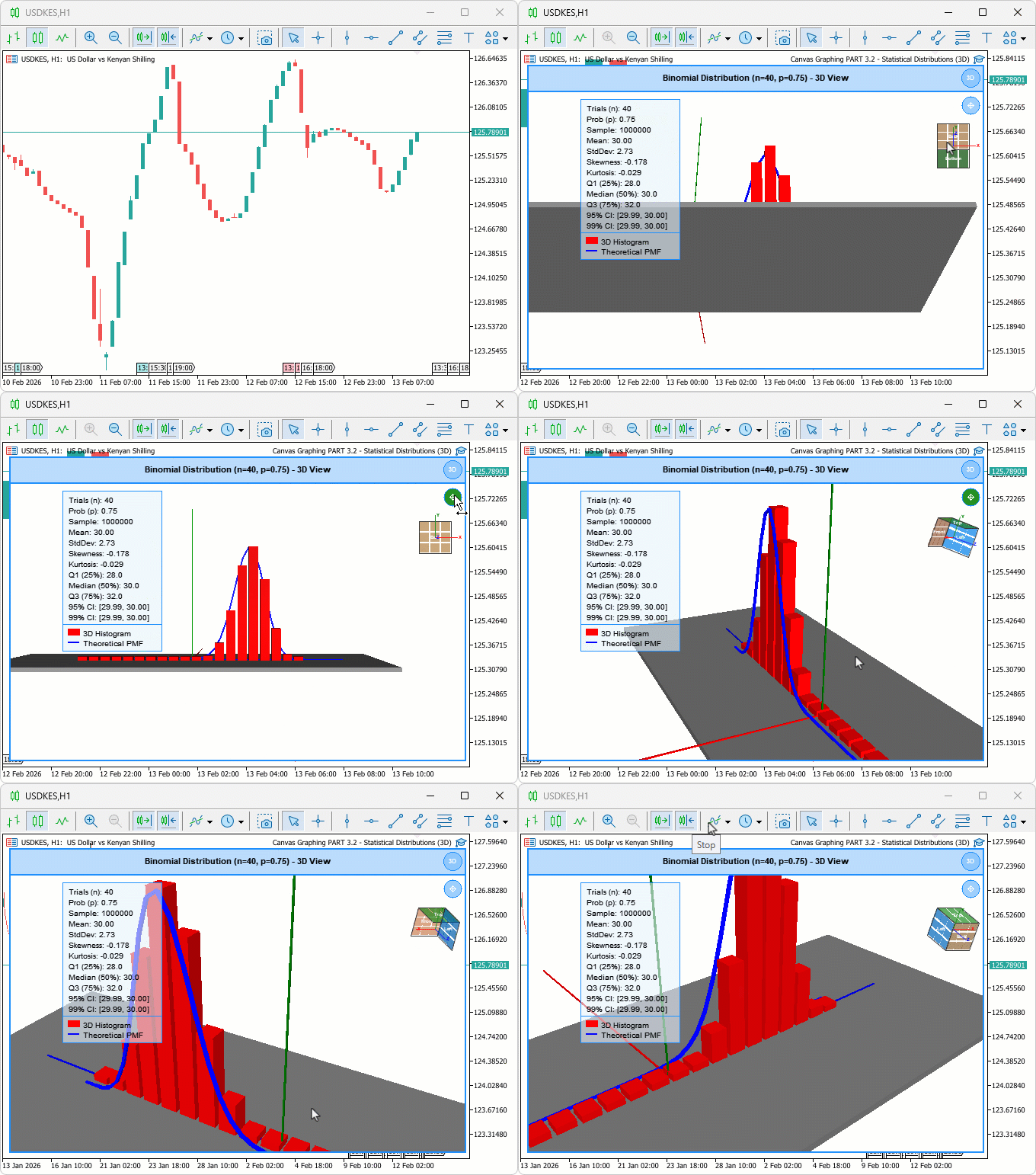
テスト中、セグメント化された3Dカーブは、異なる試行回数においてもヒストグラムバーのピークと一貫して一致しました。パンモードでは、現在の回転角度やズームレベルを変更することなく、注視点を滑らかに移動できました。また、ViewCubeのクリック操作では、テストしたすべての面・辺・頂点ゾーンにおいて、カメラが正しい標準方向へスムーズにアニメーション遷移しました。
結論
MQL5の3D二項分布ビューアを拡張し、確率質量関数を奥行き付きで正確に可視化するためのセグメント化されたチューブ状カーブ、カメラ基準で注視点を移動するパンモード、そして面・辺・頂点のホバーゾーンを備えたインタラクティブなViewCubeを実装しました。ViewCubeは標準方向へのカメラアニメーション遷移にも対応しています。実装では、ボックスベースのカーブセグメント構築と変換行列による方向付け、ホバーゾーン検出のための双線形分割、タイマー制御によるスムーズステップ型カメラ遷移、さらにクリック・パン操作・キーボードショートカットに対応したイベント処理の更新をおこないました。この記事を読み終えた今、以下のことができるでしょう。
- 3Dカーブを使用して、確率質量関数のピークが最頻度のヒストグラムビンと一致しているかを視覚的に確認する。2Dモードへ切り替えることなく、シーン上で直接モデルの適合性を判断する。
- パンモードを有効化することで、現在の回転角度やズームレベルを維持したまま、低確率領域のテール部分や広く偏在した試行回数レンジへシーンの焦点を移動する。
- ViewCube上の任意の面・辺・頂点をクリックすることで、カメラを標準方向へアニメーション移動する。上面ビューではすべてのバー高さを比較でき、正面ビューでは個々のビン値を明確に読み取る。
次回以降では、2D統計分布へ進み、さらに多くの分布をプロットしていきます。どうぞお楽しみに。
MetaQuotes Ltdにより英語から翻訳されました。
元の記事: https://www.mql5.com/en/articles/21335
警告: これらの資料についてのすべての権利はMetaQuotes Ltd.が保有しています。これらの資料の全部または一部の複製や再プリントは禁じられています。
この記事はサイトのユーザーによって執筆されたものであり、著者の個人的な見解を反映しています。MetaQuotes Ltdは、提示された情報の正確性や、記載されているソリューション、戦略、または推奨事項の使用によって生じたいかなる結果についても責任を負いません。

 コード、涙、そしてAlgo Forge
 MQL5とデータ処理パッケージの統合(第8回):グラフニューラルネットワークによる流動性ゾーンの検出
 取引におけるニューラルネットワーク:周波数領域での異常検知(最終回)
 プライスアクション分析ツールキットの開発(第64回):手動で描画したトレンドラインと自動監視の同期

- 無料取引アプリ
- 8千を超えるシグナルをコピー
- 金融ニュースで金融マーケットを探索
3D曲線が表示されません
現在、3Dカーブセグメントの位置決めはシーンのレンダリング完了後、1ステップ遅れて行われるため、最初の静止フレームではまだ配置されていません。キャンバス上で1回、オービット(左クリック&ドラッグ)またはズーム(スクロールホイール)を行ってください。これにより再度レンダリングが実行され、カーブが表示されます。
3D表示に切り替えた瞬間にカーブをレンダリングさせたい場合は、カーブのレンダリング関数をレンダリング呼び出しの前に移動させてください。以下を参照してください:
変更前:
変更後:
ご指摘ありがとうございます。お役に立てれば幸いです。ありがとうございます。
3D曲線が表示されない
現在、3D曲線のセグメントはシーンのレンダリングが行われる1ステップ後に配置されるため、最初の静止画にはまだ表示されていません。 キャンバス上で一度、回転(左クリックでドラッグ)またはズーム(スクロールホイール)を行ってください。これにより再レンダリングが実行され、曲線が表示されます。
3D表示に切り替えた瞬間に曲線が即座にレンダリングされるようにしたい場合は、曲線のレンダリング処理を、シーン全体のレンダリング呼び出しの前に移動させてください。以下を参照してください:
変更前:
変更後:
ご指摘ありがとうございます。お役に立てれば幸いです。ありがとうございます。
正確には、正しく理解されていませんでした。
3D曲線はなく、2D曲線のみです。 特に記事では、正しい用語を使うことが重要です。
こちらが3D曲線の例です。3次元空間にある曲線の場合、その曲線を任意の平面に投影しても、あなたのケースのように直線になることは決してありません。
私の話を聞いていなかったんですね。
というか、正しく聞いていなかったということですね。
3Dの曲線など存在せず、あるのは2Dの曲線だけです。特に記事では、正しい用語を使うことが重要です。
こちらが3D曲線の例です。曲線が3次元空間にある場合、その曲線を任意の平面に投影しても、あなたのケースのように直線になることは決してありません。
なるほど、おっしゃる意味がわかりました。ごもっともです。用語に関してはご指摘の通りです。厳密に言えば、これは平面曲線(Z軸は固定で、成功回数と確率のみが変動する)ですので、本来の意味での3D曲線ではありません。その点は承知しました。
私の意図は、PMFを3Dシーン内の実際のオブジェクトとしてレンダリングすることでした。回転可能で、チューブ状の形状を持ち、3Dヒストグラムの棒グラフの横に配置し、レンダリング時にそれらと位置が揃ったままになり、同じ空間内で両方を一緒に追跡できるようにするというものです。 つまり、「3D」とは、真の空間曲線という意味ではなく、3Dビュー内でレンダリングされるという意味で用いました。ご指摘ありがとうございます。