
MetaTrader 5에서 DirectX를 사용하여 3D 그래픽을 만드는 방법

3차원 컴퓨터 그래픽은 평면 디스플레이에 3차원 물체의 형상이 나타나게 합니다. 이러한 객체와 뷰어의 위치는 시간이 지남에 따라 변경될 수 있습니다. 따라서 2차원 그림도 변경하여 이미지 깊이의 착시를 만들 수 있습니다. 그러기 위해서는 회전, 확대/축소, 조명등이 변경 되도록 지원해야 합니다. MQL5를 사용하면DirectX 함수를 사용하여 MetaTrader 5 터미널에서 컴퓨터 그래픽을 직접 만들고 관리할 수 있습니다. 이들 함수가 작동하려면 비디오 카드가DX 11및 Shader Model 5.0을 지원해야 합니다.
- 객체 모델링
- 모양 만들기
- 장면 계산 및 렌더링
- Z축 및 뷰 포인트를 중심으로 한 객체 회전
- 카메라 위치 관리
- 객체 색상 관리
- 회전 및 이동
- 조명 작업
- 애니메이션
- 마우스를 사용하여 카메라 위치 제어
- 텍스처 적용
- 사용자 정의 객체 만들기
- 데이터 기반 3D 표면
객체 모델링
평면 공간에 3차원 물체를 그리기 위해서는 먼저 이 물체의 X, Y, Z 좌표 모델을 구해야 합니다. 이는 물체 표면의 각 점에 좌표를 지정해 주어야 한다는 것을 의미합니다. 이상적으로는 스케일링 중에 이미지의 품질을 유지하기 위해서는 물체의 표면에 무한한 수의 점을 찍어야 합니다. 보통은 3D 모델에서는 다각형으로 구성된 메쉬를 사용하여 작업합니다. 더 많은 수의 다각형이 있는 더 상세한 메쉬는 더 사실적인 모델을 제공합니다. 그러나 이러한 모델을 계산하고 3D 그래픽을 렌더링하기 위해서는 더 많은 컴퓨터 리소스가 필요합니다.

다각형 메쉬로 만든 찻주전자 모델.
다각형을 삼각형으로 나누는 것은 초창기의 컴퓨터와 같이 그래픽이 약한 컴퓨터에서 좋지 않은 그래픽 카드를 통해 실행되어야 했던 오래 전의 일입니다. 삼각형을 사용하면 표면의 작은 면적의 위치를 정확하게 나타낼 수 있을 뿐만 아니라 조명이나 빛 반사와 같은 관련된 매개변수를 계산할 수 있습니다. 이러한 작은 삼각형들이 모이면 물체의 3차원 이미지를 사실적으로 만들 수 있습니다. 이하에서는 꼭짓점이 N인 다각형보다 꼭짓점이 N인 삼각형을 사용하는 것이 훨씬 쉽기 때문에 다각형과 삼각형을 동의어로 사용합니다.
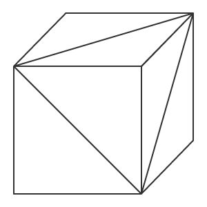
삼각형으로 이루어진 큐브.
물체의 3차원 모델은 삼각형의 각 꼭짓점의 좌표를 기술함으로써 만들 수 있습니다. 이는 물체가 움직이거나 보는 사람의 위치가 변하더라도 물체의 각 점에 대한 좌표를 추가로 계산할 수 있게 합니다. 따라서 우리는 꼭짓점과 꼭짓점을 연결하는 모서리 및 모서리에 의해 형성되는 면을 다룹니다. 삼각형의 위치를 알면 선형 대수학의 법칙을 사용하여 면에 대한 법선을 만들 수 있습니다(법선은 표면에 수직인 벡터입니다). 이렇게 하면 얼굴에 조명이 비춰지는 방식과 얼굴에서 빛이 반사되는 방식을 계산할 수 있습니다.
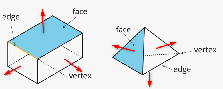
정점, 가장자리, 면 및 법선이 있는 객체의 예. 법선은 빨간색 화살표입니다.
모델 객체는 다양한 방법으로 만들 수 있습니다. 토폴로지는 다각형이 어떻게 3D 메쉬를 형성하는지를 설명합니다. 좋은 토폴로지는 최소한의 다각형을 사용하여 객체를 설명하고 객체를 더 쉽게 이동하고 회전할 수 있도록 합니다.
 두 토폴로지의 의 구 모델
두 가지 토폴로지의 구형 모델.
볼륨 효과는 객체 다각형에 빛과 그림자를 사용하여 생성됩니다. 따라서 3D 컴퓨터 그래픽의 목적은 물체의 각 점의 위치를 계산하여 빛과 그림자를 계산하여 화면에 표시하는 것입니다.
모양 만들기
큐브를 생성하는 간단한 프로그램을 작성해 보겠습니다. 3D 그래픽 라이브러리의 CCanvas3D 클래스를 사용하세요.
3D 창을 렌더링하는 CCanvas3DWindow 클래스에는 최소한의 멤버와 메서드가 있습니다. DirectX 작업을 위한 함수에 구현된 3D 그래픽 개념에 대한 설명과 함께 새로운 메서드를 점차 추가할 것입니다.
//+------------------------------------------------------------------+
//| Application window                                               |
//+------------------------------------------------------------------+
class CCanvas3DWindow
  {
protected:
   CCanvas3D         m_canvas;
   //--- canvas size
   int               m_width;
   int               m_height;
   //--- the Cube object
   CDXBox            m_box;

public:
                     CCanvas3DWindow(void) {}
                    ~CCanvas3DWindow(void) {m_box.Shutdown();}
   //-- create a scene
   virtual bool      Create(const int width,const int height){}
   //--- calculate the scene
   void              Redraw(){}
   //--- handle chart events
   void              OnChartChange(void) {}
  };
장면의 생성은 캔버스를 생성함으로써 시작됩니다. 그런 다음 프로젝션 행렬에 다음과 같은 매개변수가 설정됩니다.
- 3D 장면을 보는 방향의 30도 화각(M_PI/6)
- 가로 세로 비율
- 근거리(0.1f) 및 원거리(100.f) 클리핑 평면까지의 거리
이는 이 두 가상의 벽(0.1f 및 100.f) 사이의 객체만 투영 행렬에서 렌더링 한다는 뜻입니다. 또한 물체는 수평 30도의 화각에 있어야 합니다. 컴퓨터 그래픽의 모든 좌표와 거리가 가상이라는 점에 주목하십시오. 중요한 것은 거리와 크기 간의 관계이지 절대값이 아닙니다.
   //+------------------------------------------------------------------+
   //| Create                                                           |
   //+------------------------------------------------------------------+
   virtual bool      Create(const int width,const int height)
     {
      //--- save canvas dimensions
      m_width=width;
      m_height=height;
      //--- create a canvas to render a 3D scene
      ResetLastError();
      if(!m_canvas.CreateBitmapLabel("3D Sample_1",0,0,m_width,m_height,COLOR_FORMAT_ARGB_NORMALIZE))
        {
         Print("Error creating canvas: ",GetLastError());
         return(false);
         }
      //--- set projection matrix parameters - angle of view, aspect ratio, distance to the near and far clip planes
      m_canvas.ProjectionMatrixSet((float)M_PI/6,(float)m_width/m_height,0.1f,100.0f);
      //--- create cube - pass to it the resource manager, scene parameters and coordinates of two opposite corners of the cube
      if(!m_box.Create(m_canvas.DXDispatcher(),m_canvas.InputScene(),DXVector3(-1.0,-1.0,5.0),DXVector3(1.0,1.0,7.0)))
        {
         m_canvas.Destroy();
         return(false);
         }
      //--- add the cube to the scene
      m_canvas.ObjectAdd(&m_box);
      //--- redraw the scene
      Redraw();
      //--- succeed
      return(true);
      }
투영 행렬을 만든 후 CDXBox 클래스를 기반으로 하는 큐브인 3D 객체를 만드는 과정으로 이어집니다. 큐브를 만들려면 큐브의 반대쪽 모서리를 가리키는 두 벡터를 지정하면 됩니다. 디버그 모드에서 큐브의 생성을 관찰하면 DXComputeBox()에서 어떤 일이 발생하는지 알 수 있습니다: 모든 큐브의 정점이 생성되고(해당 좌표는 '정점' 배열에 기록됨) 큐브의 가장자리가 'indiсes' 배열에 열거되고 저장되도록 삼각형으로 나눕니다. 큐브는 8개의 꼭짓점과 12개의 삼각형으로 분할된 6개의 면을 가지고 36개의 인덱스가 이 삼각형의 꼭짓점인 열거형으로 이루어집니다.
큐브에는 8개의 정점만 있지만 6개의 면 각각에 대해 법선을 갖는 별도의 정점 세트를 지정해야 하므로 이를 설명하기 위해 24개의 벡터가 생성됩니다. 법선의 방향은 각 면에 대한 조명을 계산하는데 영향을 미칩니다. 삼각형의 꼭짓점이 인덱스에 나열되는 순서에 따라 어느 면이 보이게 될지가 결정됩니다. 꼭짓점과 인덱스가 채워지는 순서는 DXUtils.mqh 코드에서 찾아볼 수 있습니다:
   for(int i=20; i<24; i++)
      vertices[i].normal=DXVector4(0.0,-1.0,0.0,0.0);
각 면의 텍스처 매핑을 위한 텍스처 좌표도 동일한 코드에 설명되어 있습니다:
//--- texture coordinates
   for(int i=0; i<faces; i++)
     {
      vertices[i*4+0].tcoord=DXVector2(0.0f,0.0f);
      vertices[i*4+1].tcoord=DXVector2(1.0f,0.0f);
      vertices[i*4+2].tcoord=DXVector2(1.0f,1.0f);
      vertices[i*4+3].tcoord=DXVector2(0.0f,1.0f);
      }
각각의 4개의 면 벡터는 텍스처 매핑을 위한 4개의 각도 중 하나를 설정합니다. 이것은 텍스처를 렌더링하기 위해 분대 구조가 각 큐브의 면에 매핑 된다는 것을 의미합니다. 물론 이것은 텍스처가 설정된 경우에만 필요합니다.
장면 계산 및 렌더링
3D 장면이 변경될 때마다 모든 계산을 새로 수행해야 합니다. 필요한 계산 순서는 다음과 같습니다:
- 월드 좌표에서 각 객체의 중심 계산
- 객체의 각 요소, 즉 각 정점의 위치를 계산
- 뷰어에 대한 픽셀의 깊이 및 가시성 결정
- 꼭짓점으로 지정된 다각형에서 각 픽셀의 위치를 계산
- 지정된 텍스처에 따라 다각형의 각 픽셀의 색상을 설정
- 빛 픽셀의 방향과 반사를 계산
- 각 픽셀에 확산광 적용
- 모든 월드 좌표를 카메라 좌표로 변환
- 카메라 좌표를 투영 행렬의 좌표로 변환
   //+------------------------------------------------------------------+
   //| Update the scene                                                 |
   //+------------------------------------------------------------------+
   void              Redraw()
     {
      //--- calculate the 3D scene
      m_canvas.Render(DX_CLEAR_COLOR|DX_CLEAR_DEPTH,ColorToARGB(clrBlack));
      //--- update the picture on the canvas in accordance with the current scene
      m_canvas.Update();
      }
이 예에서는 큐브는 한 번만 생성되며 더 이상 변경되지 않습니다. 따라서 캔버스의 프레임은 차트 크기 조정과 같이 차트에 변경 사항이 있는 경우에만 변경하면 됩니다. 이 경우 캔버스 차원이 현재 차트의 차원으로 조정되고 투영 행렬이 재설정되며 캔버스의 이미지가 업데이트됩니다.
   //+------------------------------------------------------------------+
   //| Process chart change event                                       |
   //+------------------------------------------------------------------+
   void              OnChartChange(void)
     {
      //--- get current chart sizes
      int w=(int)ChartGetInteger(0,CHART_WIDTH_IN_PIXELS);
      int h=(int)ChartGetInteger(0,CHART_HEIGHT_IN_PIXELS);
      //--- update canvas dimensions in accordance with the chart size
      if(w!=m_width || h!=m_height)
        {
         m_width =w;
         m_height=h;
         //--- resize canvas
         m_canvas.Resize(w,h);
         DXContextSetSize(m_canvas.DXContext(),w,h);
         //--- update projection matrix in accordance with the canvas sizes
         m_canvas.ProjectionMatrixSet((float)M_PI/6,(float)m_width/m_height,0.1f,100.0f);
         //--- recalculate 3D scene and render it onto the canvas
         Redraw();
         }
      }
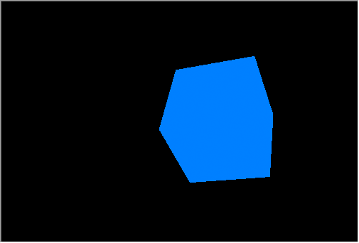
"Step1 Create Box.mq5" EA를 실행합니다. 검정색 배경에 흰색 사각형이 표시되는 것을 볼 수 있습니다. 기본적으로 생성 될 때 객체에 흰색이 설정됩니다. 조명이 아직 설정되지 않았습니다.

흰색 큐브와 공간에서 레이아웃
X축은 오른쪽으로 Y는 위쪽으로 Z는 3D 장면 안쪽으로 향합니다. 이러한 좌표 시스템을 왼손잡이라고 합니다.
큐브의 중심은 좌표 X=0, Y=0, Z=6인 점에 있습니다. 큐브를 보는 위치는 기본값인 좌표의 중심입니다. 3D 장면을 보는 위치를 변경하려면ViewPositionSet()함수를 사용하여 적절한 좌표를 명시적으로 설정합니다.
프로그램 작업을 완료하려면 "Escape"를 누르십시오.
Z축 및 뷰 포인트를 중심으로 한 객체 회전
장면에 애니메이션을 적용하려면 Z축을 중심으로 큐브 회전을 활성화합니다. 이렇게 하려면 타이머를 추가하세요. - 이벤트에 따라 큐브가 시계 반대 방향으로 회전합니다.
DXMatrixRotationZ() 메서드를 사용하여 주어진 각도로 Z축을 중심으로 회전할 수 있도록 회전 행렬을 만듭니다. 그런 다음 회전 행렬을 TransformMatrixSet() 메서드에 매개 변수로 전달합니다. 이렇게 하면 3D 공간에서 큐브의 위치가 변경됩니다. 다시 Redraw()를 호출하여 캔버스의 이미지를 업데이트합니다.
   //+------------------------------------------------------------------+
   //| Timer handler                                                    |
   //+------------------------------------------------------------------+
   void              OnTimer(void)
     {
      //--- variables for calculating the rotation angle
      static ulong last_time=0;
      static float angle=0;
      //--- get the current time
      ulong current_time=GetMicrosecondCount();
      //--- calculate the delta
      float deltatime=(current_time-last_time)/1000000.0f;
      if(deltatime>0.1f)
         deltatime=0.1f;
      //--- increase the angle of rotation of the cube around the Z axis
      angle+=deltatime;
      //--- remember the time
      last_time=current_time;
      //--- set the angle of rotation of the cube around the Z axis
      DXMatrix rotation;
      DXMatrixRotationZ(rotation,angle);
      m_box.TransformMatrixSet(rotation);
      //--- recalculate 3D scene and render it onto the canvas
      Redraw();
      }
실행을 하면 회전하는 흰색 사각형이 표시됩니다.
큐브는 Z축을 중심으로 시계 반대 방향으로 회전합니다.
이 예제의 소스 코드는"Step2 Rotation Z.mq5" 파일에서 찾을 수 있습니다. 이제 장면을 만들 때 각도M_PI/5가 지정됩니다. 이전 예제의 각도 M_PI/6보다 큽니다.
      //--- set projection matrix parameters - angle of view, aspect ratio, distance to the near and far clip planes
      m_matrix_view_angle=(float)M_PI/5;
      m_canvas.ProjectionMatrixSet(m_matrix_view_angle,(float)m_width/m_height,0.1f,100.0f);
      //--- create cube - pass to it the resource manager, scene parameters and coordinates of two opposite corners of the cube
그러나 화면의 큐브 차원은 시각적으로는 더 작습니다. 투영 매트릭스를 설정할 때 지정한 화각이 작을수록 물체가 차지하는 프레임 부분이 커집니다. 이것은 망원경으로 물체를 보는 것과 마찬가지입니다. 물체는 더 크지만 화각은 더 작습니다.
카메라 위치 관리
CCanvas3D 클래스에는 상호 연결된 3D 장면 매개변수를 설정하는 세 가지 방법이 있습니다.
- ViewPositionSet은 3D 장면의 시점을 설정합니다.
- ViewTargetSet은 응시점의 좌표를 설정합니다.
- ViewUpDirectionSet은 3D 공간에서 프레임 위쪽 테두리의 방향을 설정합니다.
이 모든 매개변수는 함께 사용됩니다. 즉 3D 장면에서 이러한 매개변수를 설정하려면 다른 두 매개변수도 초기화해야 합니다. 이것은 적어도 장면 생성 단계에서 수행되어야 합니다. 이것은 프레임의 위쪽 테두리가 왼쪽과 오른쪽으로 흔들리는 다음 예에서 볼 수 있습니다. 스윙은 Create() 메서드에 다음 세 줄의 코드를 추가하여 구현됩니다.
   //+------------------------------------------------------------------+
   //| Create                                                           |
   //+------------------------------------------------------------------+
   virtual bool      Create(const int width,const int height)
     {
....
      //--- add the cube to the scene
      m_canvas.ObjectAdd(&m_box);
      //--- set the scene parameters
      m_canvas.ViewUpDirectionSet(DXVector3(0,1,0));  // set the direction vector up, along the Y axis
      m_canvas.ViewPositionSet(DXVector3(0,0,0));     // set the viewpoint from the center of coordinates
      m_canvas.ViewTargetSet(DXVector3(0,0,6));       // set the gaze point at center of the cube
      //--- redraw the scene
      Redraw();
      //--- succeed
      return(true);
      }
수평선 벡터가 좌우로 흔들리도록 하기 위해 OnTimer() 메서드를 수정합니다.
   //+------------------------------------------------------------------+
   //| Timer handler                                                    |
   //+------------------------------------------------------------------+
   void              OnTimer(void)
     {
      //--- variables for calculating the rotation angle
      static ulong last_time=0;
      static float max_angle=(float)M_PI/30;
      static float time=0;
      //--- get the current time
      ulong current_time=GetMicrosecondCount();
      //--- calculate the delta
      float deltatime=(current_time-last_time)/1000000.0f;
      if(deltatime>0.1f)
         deltatime=0.1f;
      //--- increase the angle of rotation of the cube around the Z axis
      time+=deltatime;
      //--- remember the time
      last_time=current_time;
      //--- set the rotation angle around the Z axis
      DXVector3 direction=DXVector3(0,1,0);     // initial direction of the top
      DXMatrix rotation;                        // rotation vector
      //--- calculate the rotation matrix
      DXMatrixRotationZ(rotation,float(MathSin(time)*max_angle));
      DXVec3TransformCoord(direction,direction,rotation);
      m_canvas.ViewUpDirectionSet(direction);   // set the new direction of the top
      //--- recalculate 3D scene and render it onto the canvas
      Redraw();
      }
예제를"Step3 ViewUpDirectionSet.mq5"로 저장하고 실행합니다. 실제로는 움직이지 않지만 흔들리는 큐브의 이미지를 볼 수 있습니다. 이 효과는 카메라 자체가 좌우로 흔들릴 때와 마찬가지입니다.

상단의 위쪽이 흔들립니다.
객체 색상 관리
카메라를 이동하면서 코드를 수정하고 큐브가 좌표의 중심에 놓아지도록 해 봅시다.
   //+------------------------------------------------------------------+
   //| Create                                                           |
   //+------------------------------------------------------------------+
   virtual bool      Create(const int width,const int height)
     {
  ...
      //--- create cube - pass to it the resource manager, scene parameters and coordinates of two opposite corners of the cube
      if(!m_box.Create(m_canvas.DXDispatcher(),m_canvas.InputScene(),DXVector3(-1.0,-1.0,-1.0),DXVector3(1.0,1.0,1.0)))
        {
         m_canvas.Destroy();
         return(false);
         }
      //--- set the color
      m_box.DiffuseColorSet(DXColor(0.0,0.5,1.0,1.0));
      //--- add the cube to the scene
      m_canvas.ObjectAdd(&m_box);
      //--- set positions for camera, gaze and direction of the top
      m_canvas.ViewUpDirectionSet(DXVector3(0.0,1.0,0.0));  // set the direction vector up, along the Y axis
      m_canvas.ViewPositionSet(DXVector3(3.0,2.0,-5.0));    // set camera on the right, on top and in front of the cube
      m_canvas.ViewTargetSet(DXVector3(0,0,0));             // set the gaze direction at center of the cube
      //--- redraw the scene
      Redraw();
      //--- succeed
      return(true);
      }
또한 큐브를 파란색으로 칠해봅니다. 색상은 알파 채널(알파 채널이 마지막에 표시됨)이 있는 RGB 색상 형식으로 설정되지만 값은 1로 정규화 됩니다. 그러므로 값 1은 255를 의미하고 0.5는 127을 의미합니다.
X축을 중심으로 회전을 추가하고 변경 사항을 "Step4 Box Color.mq5"로 저장합니다.

회전하는 큐브의 오른쪽 상단 보기.
회전 및 이동
객체는 한 번에 세 방향으로 이동 및 회전할 수 있습니다. 객체 변경은 무엇이든지 행렬을 사용하여 구현됩니다. 즉 회전, 이동 및 변형은 별도로 계산할 수 있습니다. 예를 변경해 보겠습니다: 이제 카메라 뷰가 위쪽과 앞쪽에서 부터입니다.
   //+------------------------------------------------------------------+
   //| Create                                                           |
   //+------------------------------------------------------------------+
   virtual bool      Create(const int width,const int height)
     {
  ...
      m_canvas.ProjectionMatrixSet(m_matrix_view_angle,(float)m_width/m_height,0.1f,100.0f);
      //--- position the camera in top and in front of the center of coordinates
      m_canvas.ViewPositionSet(DXVector3(0.0,2.0,-5.0));
      m_canvas.ViewTargetSet(DXVector3(0.0,0.0,0.0));
      m_canvas.ViewUpDirectionSet(DXVector3(0.0,1.0,0.0));
      //--- create cube - pass to it the resource manager, scene parameters and coordinates of two opposite corners of the cube
      if(!m_box.Create(m_canvas.DXDispatcher(),m_canvas.InputScene(),DXVector3(-1.0,-1.0,-1.0),DXVector3(1.0,1.0,1.0)))
        {
         m_canvas.Destroy();
         return(false);
         }
      //--- set the cube color
      m_box.DiffuseColorSet(DXColor(0.0,0.5,1.0,1.0));
      //--- calculate the cube position and the transfer matrix
      DXMatrix rotation,translation;
      //--- rotate the cube sequentially along the X, Y and Z axes
      DXMatrixRotationYawPitchRoll(rotation,(float)M_PI/4,(float)M_PI/3,(float)M_PI/6);
      //-- move the cube to the right/downward/inward
      DXMatrixTranslation(translation,1.0,-2.0,5.0);
      //--- get the transformation matrix as a product of rotation and transfer
      DXMatrix transform;
      DXMatrixMultiply(transform,rotation,translation);
      //--- set the transformation matrix
      m_box.TransformMatrixSet(transform);
      //--- add the cube to the scene
      m_canvas.ObjectAdd(&m_box);
      //--- redraw the scene
      Redraw();
      //--- succeed
      return(true);
      }
회전 및 전송 행렬을 순차적으로 생성하고 결과 변환 행렬을 적용하고 큐브를 렌더링합니다. "Step5 Translation.mq5"에 변경 사항을 저장하고 실행합니다.
큐브의 회전과 이동
카메라는 정지된 상태로 있고 약간 위에서 좌표의 중심을 가리키도록 합니다. 큐브는 세 방향으로 회전했고 장면의 오른쪽, 아래쪽, 안쪽으로 이동했습니다.
조명 작업
사실적인 3차원 영상을 얻기 위해서는 물체 표면의 각 점의 조명을 계산해야 합니다. 이것은 Phong 셰이딩 모델을 사용하여 수행되며 이는 주변, 확산 및 반사광과 같은 세 가지 조명 구성 요소의 색상 강도를 계산합니다. 여기에서 사용되는 매개변수는 다음과 같습니다.
- DirectionLight — 방향 조명의 방향은 CCanvas3D에서 설정됩니다.
- AmbientLight — 앰비언트 조명의 색상과 강도는 CCanvas3D에서 설정됩니다.
- DiffuseColor — 계산된 확산 조명 구성 요소는 CDXMesh 및 해당 자식 클래스에서 설정됩니다.
- EmissionColor — 배경 조명 구성 요소는 CDXMesh 및 해당 자식 클래스에서 설정됩니다.
- SpecularColor — 반사 구성 요소는 CDXMesh 및 해당 자식 클래스에 설정됩니다.

퐁 음영 모델
조명 모델은 표준 셰이더에서 구현되고 모델 매개변수는 CCanvas3D로 설정되며 객체 매개변수는 CDXMesh 및 해당 자식 클래스에서 설정됩니다. 다음과 같이 예제를 수정합니다.
- 큐브를 좌표의 중심으로 되돌립니다.
- 큐브를 흰색으로 설정합니다.
- 위에서 아래로 장면을 비추는 노란색의 방향성 소스를 추가합니다.
- 무지향성 조명의 경우 파란색을 설정합니다.
      //--- set yellow color for the source and direct it from above downwards
      m_canvas.LightColorSet(DXColor(1.0,1.0,0.0,0.8f));
      m_canvas.LightDirectionSet(DXVector3(0.0,-1.0,0.0));
      //--- set the blue color for the ambient light
      m_canvas.AmbientColorSet(DXColor(0.0,0.0,1.0,0.4f));
      //--- create cube - pass to it the resource manager, scene parameters and coordinates of two opposite corners of the cube
      if(!m_box.Create(m_canvas.DXDispatcher(),m_canvas.InputScene(),DXVector3(-1.0,-1.0,-1.0),DXVector3(1.0,1.0,1.0)))
        {
         m_canvas.Destroy();
         return(false);
         }
      //--- set the white color for the cube
      m_box.DiffuseColorSet(DXColor(1.0,1.0,1.0,1.0));
      //--- add green glow for the cube (emission)
      m_box.EmissionColorSet(DXColor(0.0,1.0,0.0,0.2f));
Canvas3D에서는 광원의 위치가 설정되지 않고 빛이 퍼지는 방향만 알려주니 주의하시기 바랍니다. 지향성 광원은 무한한 거리에 있는 것으로 간주되며 언제나 평행한 광원 스트림으로 장면을 비춥니다.
m_canvas.LightDirectionSet(DXVector3(0.0,-1.0,0.0)); 여기에서 광 확산 벡터는 Y축을 따라 음의 방향, 즉 위에서 아래로 가리킵니다. 또한, 직접 광원(LightColorSet 및 LightDirectionSet)에 대한 매개변수를 설정하는 경우 주변 조명(AmbientColorSet)의 색상도 지정해야 합니다. 기본적으로 주변 조명의 색상은 최대 강도의 흰색으로 설정되므로 모든 그림자가 흰색이 됩니다. 즉 장면의 객체는 주변 조명의 흰색으로 넘쳐나고 방향 소스 라이트는 흰색 조명에 의해 간섭을 받습니다.
      //--- set yellow color for the source and direct it from above downwards
      m_canvas.LightColorSet(DXColor(1.0,1.0,0.0,0.8f));
      m_canvas.LightDirectionSet(DXVector3(0.0,-1.0,0.0));
      //--- set the blue color for the ambient light
      m_canvas.AmbientColorSet(DXColor(0.0,0.0,1.0,0.4f));  // must be specified
아래 gif 애니메이션은 조명을 추가할 때 이미지가 어떻게 변하는지 보여줍니다. 예제의 소스 코드는"Step6 Add Light.mq5"파일에서 사용할 수 있습니다.
 파란색 주변 조명이 있는 노란색 광원 아래에서 녹색 방출이 있는 흰색 큐브
파란색 주변 조명이 있는 노란색 광원 아래에서 녹색의 방출이 있는 흰색 큐브
작동 방식을 보려면 위의 코드에서 색상 메서드를 해제해 보세요.
애니메이션
애니메이션은 시간이 지남에 따른 장면 매개변수와 객체의 변화를 의미합니다. 사용 가능한 모든 속성은 시간 또는 이벤트에 따라 변경될 수 있습니다. 타이머를 10밀리초로 설정합니다. 이 이벤트는 장면 업데이트에 영향을 미칩니다.
int OnInit()
  {
...
//--- create canvas
   ExtAppWindow=new CCanvas3DWindow();
   if(!ExtAppWindow.Create(width,height))
      return(INIT_FAILED);
//--- set timer
   EventSetMillisecondTimer(10);
//---
   return(INIT_SUCCEEDED);
   }
CCanvas3DWindow에 적절한 이벤트 핸들러를 추가합니다. 객체 매개변수(예: 회전, 이동 및 확대/축소)와 조명 방향을 변경해야 합니다:
   //+------------------------------------------------------------------+
   //| Timer handler                                                    |
   //+------------------------------------------------------------------+
   void              OnTimer(void)
     {
      static ulong last_time=0;
      static float time=0;
      //--- get the current time
      ulong current_time=GetMicrosecondCount();
      //--- calculate the delta
      float deltatime=(current_time-last_time)/1000000.0f;
      if(deltatime>0.1f)
         deltatime=0.1f;
      //--- increase the elapsed time value
      time+=deltatime;
      //--- remember the time
      last_time=current_time;
      //--- calculate the cube position and the rotation matrix
      DXMatrix rotation,translation,scale;
      DXMatrixRotationYawPitchRoll(rotation,time/11.0f,time/7.0f,time/5.0f);
      DXMatrixTranslation(translation,(float)sin(time/3),0.0,0.0);
      //--- calculate the cube compression/extension along the axes
      DXMatrixScaling(scale,1.0f+0.5f*(float)sin(time/1.3f),1.0f+0.5f*(float)sin(time/1.7f),1.0f+0.5f*(float)sin(time/1.9f));
      //--- multiply the matrices to obtain the final transformation
      DXMatrix transform;
      DXMatrixMultiply(transform,scale,rotation);
      DXMatrixMultiply(transform,transform,translation);
      //--- set the transformation matrix
      m_box.TransformMatrixSet(transform);
      //--- calculate the rotation of the light source around the Z axis
      DXMatrixRotationZ(rotation,deltatime);
      DXVector3 light_direction;
      //--- get the current direction of the light source
      m_canvas.LightDirectionGet(light_direction);
      //--- calculate the new direction of the light source and set it
      DXVec3TransformCoord(light_direction,light_direction,rotation);
      m_canvas.LightDirectionSet(light_direction);
      //--- recalculate the 3D scene and draw it in the canvas
      Redraw();
      }
객체의 변경 사항은 초기 값에서 적용된다는 점에 유의하십시오. 우리는 언제나 초기의 큐브의 상태를 다루면서 회전/이동/압축과 관련된 모든 작업을 처음부터 적용하는 것입니다. 즉 큐브의 현재 상태는 저장되지 않는다는 의미입니다. 그러나 광원의 방향은 현재 값에서deltatime단위로 변경됩니다.

동적으로 변화하는 광원의 방향으로 회전하는 큐브.
결과는 매우 복잡한 3D 애니메이션입니다. 예제 코드는"Step7 Animation.mq5" 파일에 있습니다.
마우스를 사용하여 카메라 위치 제어
3D 그래픽의 마지막 애니메이션 요소인 사용자의 동작에 대한 반응을 살펴보겠습니다. 이 예에서는 마우스를 사용하여 카메라 관리를 추가합니다. 먼저 마우스 이벤트를 받고 해당 핸들러를 만듭니다.
int OnInit()
  {
...
//--- set the timer
   EventSetMillisecondTimer(10);
//--- enable receiving of mouse events: moving and button clicks
   ChartSetInteger(0,CHART_EVENT_MOUSE_MOVE,1);
   ChartSetInteger(0,CHART_EVENT_MOUSE_WHEEL,1)
//---
   return(INIT_SUCCEEDED);
   }
void OnDeinit(const int reason)
  {
//--- Deleting the timer
   EventKillTimer();
//--- disable the receiving of mouse events
   ChartSetInteger(0,CHART_EVENT_MOUSE_MOVE,0);
   ChartSetInteger(0,CHART_EVENT_MOUSE_WHEEL,0);
//--- delete the object
   delete ExtAppWindow;
//--- return chart to the usual display mode with price charts
   ChartSetInteger(0,CHART_SHOW,true);
   }
void OnChartEvent(const int id,const long &lparam,const double &dparam,const string &sparam)
  {
...
//--- chart change event
   if(id==CHARTEVENT_CHART_CHANGE)
      ExtAppWindow.OnChartChange();
//--- mouse movement event
   if(id==CHARTEVENT_MOUSE_MOVE)
      ExtAppWindow.OnMouseMove((int)lparam,(int)dparam,(uint)sparam);
//--- mouse wheel scroll event
   if(id==CHARTEVENT_MOUSE_WHEEL)
      ExtAppWindow.OnMouseWheel(dparam);
CCanvas3DWindow에서 마우스 이동 이벤트 핸들러를 만듭니다. 왼쪽 버튼을 누른 상태에서 마우스를 움직이면 카메라 방향의 각도가 변경됩니다.
   //+------------------------------------------------------------------+
   //| Handle mouse movements                                           |
   //+------------------------------------------------------------------+
   void              OnMouseMove(int x,int y,uint flags)
     {
      //--- left mouse button
      if((flags&1)==1)
        {
         //--- there is no information about the previous mouse position
         if(m_mouse_x!=-1)
           {
            //--- update the camera angle upon change of position
            m_camera_angles.y+=(x-m_mouse_x)/300.0f;
            m_camera_angles.x+=(y-m_mouse_y)/300.0f;
            //--- set the vertical angle in the range between (-Pi/2,Pi2)
            if(m_camera_angles.x<-DX_PI*0.49f)
               m_camera_angles.x=-DX_PI*0.49f;
            if(m_camera_angles.x>DX_PI*0.49f)
               m_camera_angles.x=DX_PI*0.49f;
            //--- update camera position
            UpdateCameraPosition();
            }
         //--- save mouse position
         m_mouse_x=x;
         m_mouse_y=y;
         }
      else
        {
         //--- reset the saved position if the left mouse button is not pressed
         m_mouse_x=-1;
         m_mouse_y=-1;
         }
      }
다음은 카메라와 장면 중심의 간의 거리를 변경하는 마우스 휠 이벤트 핸들러입니다.
   //+------------------------------------------------------------------+
   //| Handling mouse wheel events                                      |
   //+------------------------------------------------------------------+
   void              OnMouseWheel(double delta)
     {
      //--- update the distance between the camera and the center upon a mouse scroll
      m_camera_distance*=1.0-delta*0.001;
      //--- set the distance in the range between [3,50]
      if(m_camera_distance>50.0)
         m_camera_distance=50.0;
      if(m_camera_distance<3.0)
         m_camera_distance=3.0;
      //--- update camera position
      UpdateCameraPosition();
      }
두 핸들러 모두 UpdateCameraPosition() 메서드를 호출하여 업데이트된 매개변수에 따라 카메라 위치를 업데이트합니다.
   //+------------------------------------------------------------------+
   //| Updates the camera position                                      |
   //+------------------------------------------------------------------+
   void              UpdateCameraPosition(void)
     {
      //--- the position of the camera taking into account the distance to the center of coordinates
      DXVector4 camera=DXVector4(0.0f,0.0f,-(float)m_camera_distance,1.0f);
      //--- camera rotation around the X axis
      DXMatrix rotation;
      DXMatrixRotationX(rotation,m_camera_angles.x);
      DXVec4Transform(camera,camera,rotation);
      //--- camera rotation around the Y axis
      DXMatrixRotationY(rotation,m_camera_angles.y);
      DXVec4Transform(camera,camera,rotation);
      //--- set camera to position
      m_canvas.ViewPositionSet(DXVector3(camera));
      }
소스 코드는 아래의 "Step8 Mouse Control.mq5" 파일에 있습니다.
 마우스를 사용
마우스를 사용하여 카메라 위치를 제어
텍스처 적용
텍스처는 패턴이나 재료를 나타내기 위해 다각형 표면에 적용되는 비트맵 이미지입니다. 텍스처를 사용하면 표면에 작은 객체를 재현할 수 있으나 다각형을 사용해서 만들면 너무 많은 리소스가 필요합니다. 예를 들어 돌, 나무, 흙과 같은 여러 재료를 모방할 수 있습니다.
CDXMesh와 그 자식 클래스를 사용해서 텍스처를 지정할 수 있습니다. 표준 픽셀 셰이더에서 이 텍스처는 DiffuseColor와 함께 사용됩니다. 객체 애니메이션을 제거하고 돌의 질감을 적용합니다. 터미널 작업 디렉토리의MQL5\Files 폴더에 있어야 합니다.
   virtual bool      Create(const int width,const int height)
     {
  ...
      //--- set the white color for the non-directional lighting
      m_box.DiffuseColorSet(DXColor(1.0,1.0,1.0,1.0));

      //--- add texture to draw the cube faces
      m_box.TextureSet(m_canvas.DXDispatcher(),"stone.bmp");
      //--- add the cube to the scene
      m_canvas.ObjectAdd(&m_box);
      //--- redraw the scene
      Redraw();
      //--- succeed
      return(true);
      }

돌 질감의 큐브
사용자 정의 객체 만들기
모든 객체는 인덱스를 사용하여 기본 요소에 연결된 꼭짓점(DXVector3)으로 구성됩니다. 가장 일반적인 기본 요소는 삼각형입니다. 기본 3D 객체는 결합되는 기본 도형 및 기본 도형들이 결합될 정점 인덱스의 목록과 좌표를 포함하는 정점 목록을 생성하여 생성됩니다(그러나 법선, 색상 등과 같은 많은 추가 데이터도 포함할 수 있음).
표준 라이브러리에는 좌표, 조명 계산을 위한 법선, 텍스처 좌표 및 색상이 포함된 DXVertex 정점 유형이 있습니다. 표준 정점 셰이더는 이 정점 유형과 함께 작동합니다.
struct DXVertex
  {
   DXVector4         position;  // vertex coordinates
   DXVector4         normal;    // normal vector
   DXVector2         tcoord;    // face coordinate to apply the texture
   DXColor           vcolor;    // color
  };
MQL5\Include\Canvas\DXDXUtils.mqh 보조 유형에는 기본 도형의 지오메트리(꼭짓점 및 인덱스)를 생성하고 OBJ 파일에서 3D 지오메트리를 로드하기 위한 메서드 세트가 포함되어 있습니다.
구와 토러스의 생성을 추가하고 동일한 돌의 질감을 적용합니다.
   virtual bool      Create(const int width,const int height)
     {
 ...
      // --- vertices and indexes for manually created objects
      DXVertex vertices[];
      uint indices[];
      //--- prepare vertices and indices for the sphere
      if(!DXComputeSphere(0.3f,50,vertices,indices))
         return(false);
      //--- set white color for the vertices
      DXColor white=DXColor(1.0f,1.0f,1.0f,1.0f);
      for(int i=0; i<ArraySize(vertices); i++)
         vertices[i].vcolor=white;
      //--- create the sphere object
      if(!m_sphere.Create(m_canvas.DXDispatcher(),m_canvas.InputScene(),vertices,indices))
        {
         m_canvas.Destroy();
         return(false);
         }
      //--- set diffuse color for the sphere
      m_sphere.DiffuseColorSet(DXColor(0.0,1.0,0.0,1.0));
      //--- set white specular color
      m_sphere.SpecularColorSet(white);
      m_sphere.TextureSet(m_canvas.DXDispatcher(),"stone.bmp");
      //--- add the sphere to a scene
      m_canvas.ObjectAdd(&m_sphere);
      //--- prepare vertices and indices for the torus
      if(!DXComputeTorus(0.3f,0.1f,50,vertices,indices))
         return(false);
      //--- set white color for the vertices
      for(int i=0; i<ArraySize(vertices); i++)
         vertices[i].vcolor=white;
      //--- create the torus object
      if(!m_torus.Create(m_canvas.DXDispatcher(),m_canvas.InputScene(),vertices,indices))
        {
         m_canvas.Destroy();
         return(false);
         }
      //--- set diffuse color for the torus
      m_torus.DiffuseColorSet(DXColor(0.0,0.0,1.0,1.0));
      m_torus.SpecularColorSet(white);
      m_torus.TextureSet(m_canvas.DXDispatcher(),"stone.bmp");
      //--- add the torus to a scene
      m_canvas.ObjectAdd(&m_torus);
      //--- redraw the scene
      Redraw();
      //--- succeed
      return(true);
      }
새 객체에 대한 애니메이션 추가:
   void              OnTimer(void)
     {
...
      m_canvas.LightDirectionSet(light_direction);
      //--- sphere orbit
      DXMatrix translation;
      DXMatrixTranslation(translation,1.1f,0,0);
      DXMatrixRotationY(rotation,time);
      DXMatrix transform;
      DXMatrixMultiply(transform,translation,rotation);
      m_sphere.TransformMatrixSet(transform);
      //--- torus orbit with rotation around its axis
      DXMatrixRotationX(rotation,time*1.3f);
      DXMatrixTranslation(translation,-2,0,0);
      DXMatrixMultiply(transform,rotation,translation);
      DXMatrixRotationY(rotation,time/1.3f);
      DXMatrixMultiply(transform,transform,rotation);
      m_torus.TransformMatrixSet(transform);
      //--- recalculate the 3D scene and draw it in the canvas
      Redraw();
      }
변경 사항을Three Objects.mq5로 저장하고 실행합니다.

큐브 궤도에서 회전하는 물체.
데이터 기반 3D 표면
선형 차트, 히스토그램, 파이 다이어그램 등과 같은 다양한 그래프는 일반적으로 보고서를 작성하고 데이터를 분석하는 데 사용됩니다. MQL5는 2D 차트만 작성할 수 있는 그래픽 라이브러리를 제공합니다.
CDXSurface 클래스를 사용하면 2차원 배열에 저장된 사용자 지정 데이터를 사용해서 표면을 시각화 할 수 있습니다. 다음 수학적인 함수의 예를 살펴보겠습니다.
z=sin(2.0*pi*sqrt(x*x+y*y))
표면을 그릴 객체와 데이터를 저장할 배열을 만듭니다:
   virtual bool      Create(const int width,const int height)
     {
...
      //--- prepare an array to store data
      m_data_width=m_data_height=100;
      ArrayResize(m_data,m_data_width*m_data_height);
      for(int i=0;i<m_data_width*m_data_height;i++)
         m_data[i]=0.0;
      //--- create a surface object
      if(!m_surface.Create(m_canvas.DXDispatcher(),m_canvas.InputScene(),m_data,m_data_width,m_data_height,2.0f,
                           DXVector3(-2.0,-0.5,-2.0),DXVector3(2.0,0.5,2.0),DXVector2(0.25,0.25),
                           CDXSurface::SF_TWO_SIDED|CDXSurface::SF_USE_NORMALS,CDXSurface::CS_COLD_TO_HOT))
        {
         m_canvas.Destroy();
         return(false);
         }
      //--- create texture and reflection
      m_surface.SpecularColorSet(DXColor(1.0,1.0,1.0,1.0));
      m_surface.TextureSet(m_canvas.DXDispatcher(),"checker.bmp");
      //--- add the surface to the scene
      m_canvas.ObjectAdd(&m_surface);
      //--- succeed
      return(true);
      }
표면은 밑면이 4x4이고 높이가 1인 상자 안에 그려집니다. 텍스처 크기는 0.25x0.25입니다.
- SF_TWO_SIDED는 카메라가 표면 아래로 이동할 경우 표면 위와 아래 모두에 표면이 그려질 것임을 나타냅니다.
- SF_USE_NORMALS는 방향성 광원으로 인해 생기는 표면의 반사를 계산하는 데 일반적인 계산이 사용됨을 나타냅니다.
- CS_COLD_TO_HOT은 표면의 히트맵 색상을 녹색에서 노란색으로 전환되는 효과가 있는 파란색에서 빨간색으로 설정합니다.
표면을 애니메이션 하려면 사인 기호 아래에 시간을 추가하고 타이머로 업데이트하십시오.
   void              OnTimer(void)
     {
      static ulong last_time=0;
      static float time=0;
      //--- get the current time
      ulong current_time=GetMicrosecondCount();
      //--- calculate the delta
      float deltatime=(current_time-last_time)/1000000.0f;
      if(deltatime>0.1f)
         deltatime=0.1f;
      //--- increase the elapsed time value
      time+=deltatime;
      //--- remember the time
      last_time=current_time;
      //--- calculate surface values taking into account time changes
      for(int i=0; i<m_data_width; i++)
        {
         double x=2.0*i/m_data_width-1;
         int offset=m_data_height*i;
         for(int j=0; j<m_data_height; j++)
           {
            double y=2.0*j/m_data_height-1;
            m_data[offset+j]=MathSin(2.0*M_PI*sqrt(x*x+y*y)-2*time);
            }
         }
      //--- update data to draw the surface
      if(m_surface.Update(m_data,m_data_width,m_data_height,2.0f,
                          DXVector3(-2.0,-0.5,-2.0),DXVector3(2.0,0.5,2.0),DXVector2(0.25,0.25),
                          CDXSurface::SF_TWO_SIDED|CDXSurface::SF_USE_NORMALS,CDXSurface::CS_COLD_TO_HOT))
        {
         //--- recalculate the 3D scene and draw it in the canvas
         Redraw();
         }
      }
소스 코드는3D Surface.mq5에서 사용할 수 있으며 프로그램의 예제는 비디오에 나와 있습니다.
이 기사에서는 시각적 데이터 분석을 위한 간단한 기하학적 모양과 애니메이션 3D 그래픽을 만드는 DirectX 함수의 기능에 대해 알아봤습니다. 더 복잡한 예는 MetaTrader 5 터미널 설치 디렉토리에서 찾을 수 있습니다: Expert Advisors "Correlation Matrix 3D" 및 "Math 3D Morpher" 및 "Remnant 3D" 스크립트.
MQL5를 사용하면 타사의 패키지를 사용하지 않고도 알고리즘 거래와 관련한 작업을 해결할 수 있습니다.
- 많은 수의 입력 매개변수를 가진 복잡한 거래 전략의 최적화
- 최적화 결과 얻기
- 편리한 3차원 스토어에서 데이터 시각화
MetaQuotes 소프트웨어 사를 통해 러시아어가 번역됨.
원본 기고글: https://www.mql5.com/ru/articles/7708
경고: 이 자료들에 대한 모든 권한은 MetaQuotes(MetaQuotes Ltd.)에 있습니다. 이 자료들의 전부 또는 일부에 대한 복제 및 재출력은 금지됩니다.

 Expert Advisor 개발 기초부터 (파트 10): 맞춤형 지표 액세스하기
 시각화! R 언어의 'plot'과 유사한 MQL5 그래픽 라이브러리
 Expert Advisor 개발 기초부터 (파트 11): 교차 주문 시스템(Cross order system)
 SQLite: MQL5로 SQL 데이터베이스의 처리
내 디스플레이 어댑터는 Nivada FX 1700--- 구형 제품입니다. 페츄어 레벨 10.0 만 지원합니다.
따라서 DXcpl.exe를 사용하여 MT용 강제 랩을 설정하면 모두 정상적으로 실행됩니다.
언어의 기능을 보여주기 위해 나쁘지 않습니다.
그러나 거래에 사용할 수있는 곳을 생각했지만 거래에는 거의 유용하지 않지만 아무것도 떠오르지 않았습니다.
데모를 위해 포즈의 올바른 열기, 주문 설정, 수정, 삭제, 닫기 등에 대한 모든 확인을 포함하여 오류없이 검증을 위해 추가 전송을 위해 Expert Advisor 템플릿을 작성하는 것이 좋습니다.
내 요점은 mt5에서 전문가 조언을 작성했는데 오류와 문제없이 터미널에서 거래된다는 것입니다.
나는 검증을 위해 그것을 보냈고, 많은 오류가 있으며, 각 조치에 대해 약 5 개의 수표를 작성했습니다.
거래 로봇이 시장에 게시하기 전에 어떤 수표를 통과해야합니까?
그리고 그것은 쓸모가 없었고, 나는 한 달 동안 자신을 고문했지만 여전히 많은 오류가있었습니다.
나는 침을 뱉어야했고, mt5로 전환하기가 어렵다는 것은 아무것도 아니며 mt4에는 그런 문제가 없습니다.
템플릿은 확실히 유용 할 것입니다.
또는 작동하는 템플릿에 대한 링크를 주시면 좋은 템플릿을 찾지 못했습니다.
모두에게 행운을 빕니다!
작동하는 템플릿에 대한 링크를 알려주세요. 좋은 템플릿을 찾을 수 없습니다.
h ttps:// www.mql5.com/ru/forum/93352/page78#comment_48296338
스레드 링크에 대해 진심으로 감사드립니다!
하지만 일주일 동안 읽을 예정인데 제대로 이해할 수 있을지 모르겠습니다.
제 말은 MT5에서 Expert Advisor를 위한 작업 템플릿에 대한 링크입니다(실제로 그런 템플릿이 있다면).
스레드에 대한 링크는 진심으로 감사드립니다!
하지만 읽는 데 일주일이 걸릴 것 같고 제대로 이해할 수 있을지 모르겠습니다.
검증을 거쳐야 하거든요.