
How to create 3D graphics using DirectX in MetaTrader 5

Three-dimensional computer graphics provide the impressions of three-dimensional objects on a flat display. Such objects, as well as the position of the viewer can change over time. Accordingly, the two-dimensional picture should also change to create the illusion of the image depth, i.e. it should support rotation, zooming, changes in lighting and so on. MQL5 allows creating and managing computer graphics directly in the MetaTrader 5 terminal using DirectX functions. Please note that your video card should support DX 11 and Shader Model 5.0 for the functions to work.
- Object Modeling
- Creating a Shape
- Scene Calculation and Rendering
- Object Rotation around the Z Axis and Viewpoint
- Camera Position Management
- Object Color Management
- Rotation and Movement
- Working with Lighting
- Animation
- Control Camera Position Using the Mouse
- Applying Textures
- Creating Custom Objects
- Data-Based 3D Surface
Object Modeling
To draw a three-dimensional object on a flat space, a model of this object in X, Y and Z coordinates should be obtained first. It means that each point on the object surface should be described by specifying its coordinates. Ideally, one would need to describe an infinite number of points on the object surface to preserve the image quality during scaling. In practice, 3D models are described using a mesh consisting of polygons. A more detailed mesh with a higher number of polygons provides a more realistic model. However, more computer resources are required to calculate such a model and to render 3D graphics.

A teapot model as a polygon mesh.
The division of polygons into triangles appeared long ago when early computer graphics had to run on weak graphics cards. The triangle enables the exact description of the position of a small surface part, as well as the calculation of related parameters, such as lights and light reflections. The collection of such small triangles allows creating a realistic three-dimensional image of the object. Hereinafter, the polygon and the triangle will be used as synonyms since it is much easier to imagine a triangle than a polygon with N vertices.
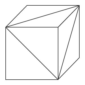
Cube made up of triangles.
A three-dimensional model of an object can be created by describing the coordinates of each vertex of the triangle, which allows further calculation of coordinates for each point of the object, even if the object moves or the viewer's position changes. Thus, we deal with vertices, the edges that connect them, and the face which is formed by the edges. If the position of a triangle is known, we can create a normal for the face using the laws of linear algebra (a normal is a vector that is perpendicular to the surface). This allows calculating how the face will be lighted and how the light will be reflected from it.
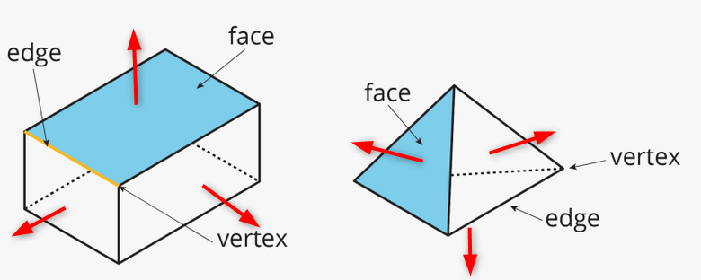
Examples of simple objects with vertices, edges, faces and normals. A normal is a red arrow.
A model object can be created in different ways. Topology describes how polygons form the 3D mesh. A good topology allows using the minimum number of polygons to describe an object and can make it easier to move and rotate the object.

Sphere model in two topologies.
The volume effect is created by using lights and shadows on the object polygons. Thus, the purpose of 3D computer graphics is to calculate the position of each point of an object, to calculate lights and shadows and to display it on the screen.
Creating a Shape
Let us write a simple program that creates a cube. Use the CCanvas3D class from the 3D graphics library.
The CCanvas3DWindow class, which renders a 3D window, has a minimum of members and methods. We will gradually add new methods with an explanation of 3D graphics concepts implemented in functions for working with DirectX.
//+------------------------------------------------------------------+
//| Application window                                               |
//+------------------------------------------------------------------+
class CCanvas3DWindow
  {
protected:
   CCanvas3D         m_canvas;
   //--- canvas size
   int               m_width;
   int               m_height;
   //--- the Cube object
   CDXBox            m_box;

public:
                     CCanvas3DWindow(void) {}
                    ~CCanvas3DWindow(void) {m_box.Shutdown();}
   //-- create a scene
   virtual bool      Create(const int width,const int height){}
   //--- calculate the scene
   void              Redraw(){}
   //--- handle chart events
   void              OnChartChange(void) {}
  };
Creation of a scene starts with the creation of a canvas. Then the following parameters are set for the projection matrix:
- A 30-degree angle of view (M_PI/6), from which we look at the 3D scene
- Aspect ratio as a ratio of width and height
- Distance to the near (0.1f) and far (100.f) clipping plane
This means that only the objects between these two virtual walls (0.1f and 100.f) will be rendered in the projection matrix. In addition, the object must fall into the horizontal 30-degree angle of view. Please note that distances as well as all the coordinates in computer graphics are virtual. What matters is the relationships between the distances and sizes, but not the absolute values.
   //+------------------------------------------------------------------+
   //| Create                                                           |
   //+------------------------------------------------------------------+
   virtual bool      Create(const int width,const int height)
     {
      //--- save canvas dimensions
      m_width=width;
      m_height=height;
      //--- create a canvas to render a 3D scene
      ResetLastError();
      if(!m_canvas.CreateBitmapLabel("3D Sample_1",0,0,m_width,m_height,COLOR_FORMAT_ARGB_NORMALIZE))
        {
         Print("Error creating canvas: ",GetLastError());
         return(false);
         }
      //--- set projection matrix parameters - angle of view, aspect ratio, distance to the near and far clip planes
      m_canvas.ProjectionMatrixSet((float)M_PI/6,(float)m_width/m_height,0.1f,100.0f);
      //--- create cube - pass to it the resource manager, scene parameters and coordinates of two opposite corners of the cube
      if(!m_box.Create(m_canvas.DXDispatcher(),m_canvas.InputScene(),DXVector3(-1.0,-1.0,5.0),DXVector3(1.0,1.0,7.0)))
        {
         m_canvas.Destroy();
         return(false);
         }
      //--- add the cube to the scene
      m_canvas.ObjectAdd(&m_box);
      //--- redraw the scene
      Redraw();
      //--- succeed
      return(true);
      }
After creating the projection matrix, we can proceed to constructing the 3D object — a cube based on the CDXBox class. To create a cube, it is enough to indicate two vectors pointing to the opposite corners of the cube. By watching the cube creation in the debug mode, you can see what is happening in DXComputeBox(): the creation of all the cube vertices (their coordinates are written to the 'vertices' array), as well as dividing of cube edges into triangles which are enumerated and saved in the 'indiсes' array. In total, the cube has 8 vertices, 6 faces which are divided into 12 triangles, and 36 indices enumerating the vertices of these triangles.
Although the cube has only 8 vertices, 24 vectors are created to describe them, since a separate set of vertices having a normal should be specified for each of the 6 faces. The direction of the normal will affect the calculation of the lighting for each face. The order in which the vertices of a triangle are listed in the index determines which of its sides will be visible. The order in which the vertices and indices are filled is shown in the DXUtils.mqh code:
   for(int i=20; i<24; i++)
      vertices[i].normal=DXVector4(0.0,-1.0,0.0,0.0);
Texture coordinates for texture mapping for each face are described in the same code:
//--- texture coordinates
   for(int i=0; i<faces; i++)
     {
      vertices[i*4+0].tcoord=DXVector2(0.0f,0.0f);
      vertices[i*4+1].tcoord=DXVector2(1.0f,0.0f);
      vertices[i*4+2].tcoord=DXVector2(1.0f,1.0f);
      vertices[i*4+3].tcoord=DXVector2(0.0f,1.0f);
      }
Each of the 4 face vectors sets one of the 4 angles for texture mapping. This means that a squad structure will be mapped to each cube face to render the texture. Of course, this is required only if the texture is set.
Scene Calculation and Rendering
All calculations should be performed anew every time the 3D scene is changed. Here is the order of required calculations:
- Calculate the center of each object in world coordinates
- Calculate the position of each element of the object, i.e. of each vertex
- Determine pixel depth and its visibility for the viewer
- Calculate the position of each pixel on the polygon specified by its vertices
- Set the color of each pixel on the polygon in accordance with the specified texture
- Calculate the direction of the light pixel and its reflection
- Apply diffused light to each pixel
- Convert all world coordinates into camera coordinates
- Convert camera coordinates into the coordinates on the projection matrix
   //+------------------------------------------------------------------+
   //| Update the scene                                                 |
   //+------------------------------------------------------------------+
   void              Redraw()
     {
      //--- calculate the 3D scene
      m_canvas.Render(DX_CLEAR_COLOR|DX_CLEAR_DEPTH,ColorToARGB(clrBlack));
      //--- update the picture on the canvas in accordance with the current scene
      m_canvas.Update();
      }
In our example, the cube is created only once, and it does not change any more. Therefore, the frame on the canvas will only need to be changed if there are changes in the chart, such as the chart resizing. In this case, the canvas dimensions are adjusted to the current chart dimensions, the projection matrix is reset and an image on the canvas is updated.
   //+------------------------------------------------------------------+
   //| Process chart change event                                       |
   //+------------------------------------------------------------------+
   void              OnChartChange(void)
     {
      //--- get current chart sizes
      int w=(int)ChartGetInteger(0,CHART_WIDTH_IN_PIXELS);
      int h=(int)ChartGetInteger(0,CHART_HEIGHT_IN_PIXELS);
      //--- update canvas dimensions in accordance with the chart size
      if(w!=m_width || h!=m_height)
        {
         m_width =w;
         m_height=h;
         //--- resize canvas
         m_canvas.Resize(w,h);
         DXContextSetSize(m_canvas.DXContext(),w,h);
         //--- update projection matrix in accordance with the canvas sizes
         m_canvas.ProjectionMatrixSet((float)M_PI/6,(float)m_width/m_height,0.1f,100.0f);
         //--- recalculate 3D scene and render it onto the canvas
         Redraw();
         }
      }
Launch the "Step1 Create Box.mq5" EA. You will see a white square on a black background. By default, white color is set for objects upon creation. Lighting has not yet been set.

A white cube and its layout in space
The X axis is directed to the right, Y is directed upward, and Z is directed inward into the 3D scene. Such a coordinate system is called left-handed.
The center of the cube is at the point with the following coordinates X=0, Y=0, Z=6. The position from which we look at the cube is in the center of coordinates, which is the default value. If you want to change the position from which the 3D scene is viewed, explicitly set appropriate coordinates using the ViewPositionSet() function.
To complete program operation, press "Escape".
Object Rotation around the Z Axis and Viewpoint
To animate the scene, let us enable cube rotation around the Z axis. To do this, add a timer — based on its events the cube will be rotated counterclockwise.
Create a rotation matrix to enable the rotation around the Z axis at a given angle using the DXMatrixRotationZ() method. Then pass it as a parameter to the TransformMatrixSet() method. This will change the position of the cube in the 3D space. Again, call Redraw() to update the image on the canvas.
   //+------------------------------------------------------------------+
   //| Timer handler                                                    |
   //+------------------------------------------------------------------+
   void              OnTimer(void)
     {
      //--- variables for calculating the rotation angle
      static ulong last_time=0;
      static float angle=0;
      //--- get the current time
      ulong current_time=GetMicrosecondCount();
      //--- calculate the delta
      float deltatime=(current_time-last_time)/1000000.0f;
      if(deltatime>0.1f)
         deltatime=0.1f;
      //--- increase the angle of rotation of the cube around the Z axis
      angle+=deltatime;
      //--- remember the time
      last_time=current_time;
      //--- set the angle of rotation of the cube around the Z axis
      DXMatrix rotation;
      DXMatrixRotationZ(rotation,angle);
      m_box.TransformMatrixSet(rotation);
      //--- recalculate 3D scene and render it onto the canvas
      Redraw();
      }
After launch, you will see a rotating white square.
The cube rotates around the Z axis counterclockwise
The source code of this example is available in the file "Step2 Rotation Z.mq5". Please note that angle M_PI/5 is specified now when creating the scene, which is greater than angle M_PI/6 from the previous example.
      //--- set projection matrix parameters - angle of view, aspect ratio, distance to the near and far clip planes
      m_matrix_view_angle=(float)M_PI/5;
      m_canvas.ProjectionMatrixSet(m_matrix_view_angle,(float)m_width/m_height,0.1f,100.0f);
      //--- create cube - pass to it the resource manager, scene parameters and coordinates of two opposite corners of the cube
However, the cube dimension in the screen are visually smaller. The smaller the angle of view specified when setting the projection matrix, the larger frame part is occupied by the object. This can be compared to seeing objects with a telescope: the object is larger, though the angle of view is smaller.
Camera Position Management
The CCanvas3D class has three methods for setting important 3D scene parameters, which are interconnected:
- ViewPositionSet sets the viewpoint of the 3D scene
- ViewTargetSet sets the coordinates of the gaze point
- ViewUpDirectionSet sets the direction of the upper border of the frame in the 3D space
All these parameters are used in combination — this means that if you want to set any of these parameters in the 3D scene, the other two parameters must also be initialized. This should be done at least at the scene generation stage. This is shown in the following example, in which the upper border of the frame swings left and right. The swing is implemented by adding the following three code lines in the Create() method:
   //+------------------------------------------------------------------+
   //| Create                                                           |
   //+------------------------------------------------------------------+
   virtual bool      Create(const int width,const int height)
     {
....
      //--- add the cube to the scene
      m_canvas.ObjectAdd(&m_box);
      //--- set the scene parameters
      m_canvas.ViewUpDirectionSet(DXVector3(0,1,0));  // set the direction vector up, along the Y axis
      m_canvas.ViewPositionSet(DXVector3(0,0,0));     // set the viewpoint from the center of coordinates
      m_canvas.ViewTargetSet(DXVector3(0,0,6));       // set the gaze point at center of the cube
      //--- redraw the scene
      Redraw();
      //--- succeed
      return(true);
      }
Modify the OnTimer() method to make the horizon vector swing left and right.
   //+------------------------------------------------------------------+
   //| Timer handler                                                    |
   //+------------------------------------------------------------------+
   void              OnTimer(void)
     {
      //--- variables for calculating the rotation angle
      static ulong last_time=0;
      static float max_angle=(float)M_PI/30;
      static float time=0;
      //--- get the current time
      ulong current_time=GetMicrosecondCount();
      //--- calculate the delta
      float deltatime=(current_time-last_time)/1000000.0f;
      if(deltatime>0.1f)
         deltatime=0.1f;
      //--- increase the angle of rotation of the cube around the Z axis
      time+=deltatime;
      //--- remember the time
      last_time=current_time;
      //--- set the rotation angle around the Z axis
      DXVector3 direction=DXVector3(0,1,0);     // initial direction of the top
      DXMatrix rotation;                        // rotation vector
      //--- calculate the rotation matrix
      DXMatrixRotationZ(rotation,float(MathSin(time)*max_angle));
      DXVec3TransformCoord(direction,direction,rotation);
      m_canvas.ViewUpDirectionSet(direction);   // set the new direction of the top
      //--- recalculate 3D scene and render it onto the canvas
      Redraw();
      }
Save the example as "Step3 ViewUpDirectionSet.mq5" and run it. You will see the image of a swinging cube, although it is actually motionless. This effect is obtained when the camera itself swings left and right.

Top direction of the top swings left and right
Object Color Management
Let us modify our code and put the cube in the center of coordinate, while moving the camera.
   //+------------------------------------------------------------------+
   //| Create                                                           |
   //+------------------------------------------------------------------+
   virtual bool      Create(const int width,const int height)
     {
  ...
      //--- create cube - pass to it the resource manager, scene parameters and coordinates of two opposite corners of the cube
      if(!m_box.Create(m_canvas.DXDispatcher(),m_canvas.InputScene(),DXVector3(-1.0,-1.0,-1.0),DXVector3(1.0,1.0,1.0)))
        {
         m_canvas.Destroy();
         return(false);
         }
      //--- set the color
      m_box.DiffuseColorSet(DXColor(0.0,0.5,1.0,1.0));
      //--- add the cube to the scene
      m_canvas.ObjectAdd(&m_box);
      //--- set positions for camera, gaze and direction of the top
      m_canvas.ViewUpDirectionSet(DXVector3(0.0,1.0,0.0));  // set the direction vector up, along the Y axis
      m_canvas.ViewPositionSet(DXVector3(3.0,2.0,-5.0));    // set camera on the right, on top and in front of the cube
      m_canvas.ViewTargetSet(DXVector3(0,0,0));             // set the gaze direction at center of the cube
      //--- redraw the scene
      Redraw();
      //--- succeed
      return(true);
      }
In addition, paint the cube in blue. The color is set in the format of an RGB color with an alpha channel (the alpha channel is indicated last), though the values are normalized to one. Thus, a value of 1 means 255, and 0.5 means 127.
Add rotation around the X axis and save changes as "Step4 Box Color.mq5".

Top right view of a rotating cube.
Rotation and Movement
Objects can be moved and rotated in three directions at a time. All object changes are implemented using matrices. Each of them, i.e. rotation, movement and transformation, can be calculated separately. Let us change the example: the camera view is now from top and front.
   //+------------------------------------------------------------------+
   //| Create                                                           |
   //+------------------------------------------------------------------+
   virtual bool      Create(const int width,const int height)
     {
  ...
      m_canvas.ProjectionMatrixSet(m_matrix_view_angle,(float)m_width/m_height,0.1f,100.0f);
      //--- position the camera in top and in front of the center of coordinates
      m_canvas.ViewPositionSet(DXVector3(0.0,2.0,-5.0));
      m_canvas.ViewTargetSet(DXVector3(0.0,0.0,0.0));
      m_canvas.ViewUpDirectionSet(DXVector3(0.0,1.0,0.0));
      //--- create cube - pass to it the resource manager, scene parameters and coordinates of two opposite corners of the cube
      if(!m_box.Create(m_canvas.DXDispatcher(),m_canvas.InputScene(),DXVector3(-1.0,-1.0,-1.0),DXVector3(1.0,1.0,1.0)))
        {
         m_canvas.Destroy();
         return(false);
         }
      //--- set the cube color
      m_box.DiffuseColorSet(DXColor(0.0,0.5,1.0,1.0));
      //--- calculate the cube position and the transfer matrix
      DXMatrix rotation,translation;
      //--- rotate the cube sequentially along the X, Y and Z axes
      DXMatrixRotationYawPitchRoll(rotation,(float)M_PI/4,(float)M_PI/3,(float)M_PI/6);
      //-- move the cube to the right/downward/inward
      DXMatrixTranslation(translation,1.0,-2.0,5.0);
      //--- get the transformation matrix as a product of rotation and transfer
      DXMatrix transform;
      DXMatrixMultiply(transform,rotation,translation);
      //--- set the transformation matrix
      m_box.TransformMatrixSet(transform);
      //--- add the cube to the scene
      m_canvas.ObjectAdd(&m_box);
      //--- redraw the scene
      Redraw();
      //--- succeed
      return(true);
      }
Sequentially create rotation and transfer matrices, apply the resulting transformation matrix and render the cube. Save changes in "Step5 Translation.mq5" and run it.

Rotation and movement of a cube
The camera is still, and it is pointed to the center of coordinates a little from above. The cube was rotated in three directions and was shifted to the right, down and inwards into the scene.
Working with Lighting
To obtain a realistic three-dimensional image, it is necessary to calculate lighting of each point on the object surface. This is done using the Phong shading model, which calculates the color intensity of the following three lighting components: ambient, diffuse and specular. The following parameters are used here:
- DirectionLight — the direction of the directional lighting is set in CCanvas3D
- AmbientLight — the color and intensity of the ambient lighting is set in CCanvas3D
- DiffuseColor — the calculated diffused lighting component is set in CDXMesh and its child classes
- EmissionColor — the background lighting component is set in CDXMesh and its child classes
- SpecularColor — the specular component is set in CDXMesh and its child classes

Phong shading model
The lighting model is implemented in standard shaders, the model parameters are set in CCanvas3D, and object parameters are set in CDXMesh and its child classes. Modify the example as follows:
- Return the cube to the center of coordinates.
- Set it to white.
- Add a directional source of yellow color that illuminates the scene from top downwards.
- Set the blue color for the non-directional lighting.
      //--- set yellow color for the source and direct it from above downwards
      m_canvas.LightColorSet(DXColor(1.0,1.0,0.0,0.8f));
      m_canvas.LightDirectionSet(DXVector3(0.0,-1.0,0.0));
      //--- set the blue color for the ambient light
      m_canvas.AmbientColorSet(DXColor(0.0,0.0,1.0,0.4f));
      //--- create cube - pass to it the resource manager, scene parameters and coordinates of two opposite corners of the cube
      if(!m_box.Create(m_canvas.DXDispatcher(),m_canvas.InputScene(),DXVector3(-1.0,-1.0,-1.0),DXVector3(1.0,1.0,1.0)))
        {
         m_canvas.Destroy();
         return(false);
         }
      //--- set the white color for the cube
      m_box.DiffuseColorSet(DXColor(1.0,1.0,1.0,1.0));
      //--- add green glow for the cube (emission)
      m_box.EmissionColorSet(DXColor(0.0,1.0,0.0,0.2f));
Please note that the position of the directed light source is not set in Canvas3D, while only the direction in which light spreads out is given. The source of the directional light is considered to be at an infinite distance and a strictly parallel light stream illuminates the scene.
m_canvas.LightDirectionSet(DXVector3(0.0,-1.0,0.0)); Here, light spreading vector is pointed along the Y axis in the negative direction, i.e. from top downwards. Furthermore, if you set parameters for the directed light source (LightColorSet and LightDirectionSet), you must also specify the color of the ambient light (AmbientColorSet). By default, the color of the ambient light is set to white with maximum intensity and thus all the shadows will be white. This means that the objects in the scene will be floodlit with white from the ambient lighting, while the directional source light will be interrupted by the white light.
      //--- set yellow color for the source and direct it from above downwards
      m_canvas.LightColorSet(DXColor(1.0,1.0,0.0,0.8f));
      m_canvas.LightDirectionSet(DXVector3(0.0,-1.0,0.0));
      //--- set the blue color for the ambient light
      m_canvas.AmbientColorSet(DXColor(0.0,0.0,1.0,0.4f));  // must be specified
The below gif animation shows how the image changes when we add lighting. The source code of the example is available in the file "Step6 Add Light.mq5".

The white cube with green emission under a yellow light source, with blue ambient light
Try to turn off color methods in the code above to see how it works.
Animation
Animation implies a change in scene parameters and objects over time. Any available properties can be changed depending on time or events. Set the timer for 10 milliseconds — this event will affect the update of the scene:
int OnInit()
  {
...
//--- create canvas
   ExtAppWindow=new CCanvas3DWindow();
   if(!ExtAppWindow.Create(width,height))
      return(INIT_FAILED);
//--- set timer
   EventSetMillisecondTimer(10);
//---
   return(INIT_SUCCEEDED);
   }
Add the appropriate event handler to CCanvas3DWindow. We need to change object parameters (such as rotation, movement and zooming) and the direction of lighting:
   //+------------------------------------------------------------------+
   //| Timer handler                                                    |
   //+------------------------------------------------------------------+
   void              OnTimer(void)
     {
      static ulong last_time=0;
      static float time=0;
      //--- get the current time
      ulong current_time=GetMicrosecondCount();
      //--- calculate the delta
      float deltatime=(current_time-last_time)/1000000.0f;
      if(deltatime>0.1f)
         deltatime=0.1f;
      //--- increase the elapsed time value
      time+=deltatime;
      //--- remember the time
      last_time=current_time;
      //--- calculate the cube position and the rotation matrix
      DXMatrix rotation,translation,scale;
      DXMatrixRotationYawPitchRoll(rotation,time/11.0f,time/7.0f,time/5.0f);
      DXMatrixTranslation(translation,(float)sin(time/3),0.0,0.0);
      //--- calculate the cube compression/extension along the axes
      DXMatrixScaling(scale,1.0f+0.5f*(float)sin(time/1.3f),1.0f+0.5f*(float)sin(time/1.7f),1.0f+0.5f*(float)sin(time/1.9f));
      //--- multiply the matrices to obtain the final transformation
      DXMatrix transform;
      DXMatrixMultiply(transform,scale,rotation);
      DXMatrixMultiply(transform,transform,translation);
      //--- set the transformation matrix
      m_box.TransformMatrixSet(transform);
      //--- calculate the rotation of the light source around the Z axis
      DXMatrixRotationZ(rotation,deltatime);
      DXVector3 light_direction;
      //--- get the current direction of the light source
      m_canvas.LightDirectionGet(light_direction);
      //--- calculate the new direction of the light source and set it
      DXVec3TransformCoord(light_direction,light_direction,rotation);
      m_canvas.LightDirectionSet(light_direction);
      //--- recalculate the 3D scene and draw it in the canvas
      Redraw();
      }
Please note that object changes are applied over initial values, as if we always deals with the initial cube state and apply all operations related to rotation/movement/compression from scratch, which means that the current state of the cube is not saved. However, the light source direction is changed by deltatime increments from the current value.

A rotating cube with the dynamically changing light source direction.
The result is a very complex 3D animation. The example code is available in the file "Step7 Animation.mq5".
Control Camera Position Using the Mouse
Let us consider the last animation element in the 3D graphics, a reaction to user actions. Add camera management using the mouse in our example. First, subscribe to mouse events and create the corresponding handlers:
int OnInit()
  {
...
//--- set the timer
   EventSetMillisecondTimer(10);
//--- enable receiving of mouse events: moving and button clicks
   ChartSetInteger(0,CHART_EVENT_MOUSE_MOVE,1);
   ChartSetInteger(0,CHART_EVENT_MOUSE_WHEEL,1)
//---
   return(INIT_SUCCEEDED);
   }
void OnDeinit(const int reason)
  {
//--- Deleting the timer
   EventKillTimer();
//--- disable the receiving of mouse events
   ChartSetInteger(0,CHART_EVENT_MOUSE_MOVE,0);
   ChartSetInteger(0,CHART_EVENT_MOUSE_WHEEL,0);
//--- delete the object
   delete ExtAppWindow;
//--- return chart to the usual display mode with price charts
   ChartSetInteger(0,CHART_SHOW,true);
   }
void OnChartEvent(const int id,const long &lparam,const double &dparam,const string &sparam)
  {
...
//--- chart change event
   if(id==CHARTEVENT_CHART_CHANGE)
      ExtAppWindow.OnChartChange();
//--- mouse movement event
   if(id==CHARTEVENT_MOUSE_MOVE)
      ExtAppWindow.OnMouseMove((int)lparam,(int)dparam,(uint)sparam);
//--- mouse wheel scroll event
   if(id==CHARTEVENT_MOUSE_WHEEL)
      ExtAppWindow.OnMouseWheel(dparam);
In CCanvas3DWindow, create the mouse movement event handler. It will change camera direction angles when the mouse is moved with the left button pressed:
   //+------------------------------------------------------------------+
   //| Handle mouse movements                                           |
   //+------------------------------------------------------------------+
   void              OnMouseMove(int x,int y,uint flags)
     {
      //--- left mouse button
      if((flags&1)==1)
        {
         //--- there is no information about the previous mouse position
         if(m_mouse_x!=-1)
           {
            //--- update the camera angle upon change of position
            m_camera_angles.y+=(x-m_mouse_x)/300.0f;
            m_camera_angles.x+=(y-m_mouse_y)/300.0f;
            //--- set the vertical angle in the range between (-Pi/2,Pi2)
            if(m_camera_angles.x<-DX_PI*0.49f)
               m_camera_angles.x=-DX_PI*0.49f;
            if(m_camera_angles.x>DX_PI*0.49f)
               m_camera_angles.x=DX_PI*0.49f;
            //--- update camera position
            UpdateCameraPosition();
            }
         //--- save mouse position
         m_mouse_x=x;
         m_mouse_y=y;
         }
      else
        {
         //--- reset the saved position if the left mouse button is not pressed
         m_mouse_x=-1;
         m_mouse_y=-1;
         }
      }
Here is the mouse wheel event handler, which changes the distance between the camera and the center of the scene:
   //+------------------------------------------------------------------+
   //| Handling mouse wheel events                                      |
   //+------------------------------------------------------------------+
   void              OnMouseWheel(double delta)
     {
      //--- update the distance between the camera and the center upon a mouse scroll
      m_camera_distance*=1.0-delta*0.001;
      //--- set the distance in the range between [3,50]
      if(m_camera_distance>50.0)
         m_camera_distance=50.0;
      if(m_camera_distance<3.0)
         m_camera_distance=3.0;
      //--- update camera position
      UpdateCameraPosition();
      }
Both handlers call the UpdateCameraPosition() method to update the camera position according to the updated parameters:
   //+------------------------------------------------------------------+
   //| Updates the camera position                                      |
   //+------------------------------------------------------------------+
   void              UpdateCameraPosition(void)
     {
      //--- the position of the camera taking into account the distance to the center of coordinates
      DXVector4 camera=DXVector4(0.0f,0.0f,-(float)m_camera_distance,1.0f);
      //--- camera rotation around the X axis
      DXMatrix rotation;
      DXMatrixRotationX(rotation,m_camera_angles.x);
      DXVec4Transform(camera,camera,rotation);
      //--- camera rotation around the Y axis
      DXMatrixRotationY(rotation,m_camera_angles.y);
      DXVec4Transform(camera,camera,rotation);
      //--- set camera to position
      m_canvas.ViewPositionSet(DXVector3(camera));
      }
The source code is available in the "Step8 Mouse Control.mq5" file below.

Control camera position using the mouse.
Applying Textures
A texture is a bitmap image that is applied to the surface of a polygon to represent patterns or materials. The use of textures allows reproduce small objects on the surface, which would require too many resources if we created them using polygons. For example, this can be an imitation of a stone, wood, soil and other materials.
CDXMesh and its child classes allow specifying texture. In the standard pixel shader this texture is used together with DiffuseColor. Remove the object animation and apply a stone texture. It should be located in the MQL5\Files folder of the terminal working directory:
   virtual bool      Create(const int width,const int height)
     {
  ...
      //--- set the white color for the non-directional lighting
      m_box.DiffuseColorSet(DXColor(1.0,1.0,1.0,1.0));

      //--- add texture to draw the cube faces
      m_box.TextureSet(m_canvas.DXDispatcher(),"stone.bmp");
      //--- add the cube to the scene
      m_canvas.ObjectAdd(&m_box);
      //--- redraw the scene
      Redraw();
      //--- succeed
      return(true);
      }

A cube with a stone texture.
Creating Custom Objects
All objects consist of vertices (DXVector3), which are connected into primitives using indices. The most common primitive is a triangle. A basic 3D object is created by creating a list of vertices which contain at least coordinates (but can also contain a lot of additional data, such as normal, color, etc.), the type of primitives into which they are combined, and a list of vertex indices by which they will be combined into primitives.
The Standard Library has the DXVertex vertex type, which contains its coordinate, a normal for lighting calculation, texture coordinates and color. The standard vertex shader works with this vertex type.
struct DXVertex
  {
   DXVector4         position;  // vertex coordinates
   DXVector4         normal;    // normal vector
   DXVector2         tcoord;    // face coordinate to apply the texture
   DXColor           vcolor;    // color
  };
The MQL5\Include\Canvas\DXDXUtils.mqh auxiliary type contains a set of methods for generating the geometry (vertices and indices) of the basic primitives and for loading 3D geometry from .OBJ files.
Add the creation of a sphere and a torus, apply the same stone texture:
   virtual bool      Create(const int width,const int height)
     {
 ...
      // --- vertices and indexes for manually created objects
      DXVertex vertices[];
      uint indices[];
      //--- prepare vertices and indices for the sphere
      if(!DXComputeSphere(0.3f,50,vertices,indices))
         return(false);
      //--- set white color for the vertices
      DXColor white=DXColor(1.0f,1.0f,1.0f,1.0f);
      for(int i=0; i<ArraySize(vertices); i++)
         vertices[i].vcolor=white;
      //--- create the sphere object
      if(!m_sphere.Create(m_canvas.DXDispatcher(),m_canvas.InputScene(),vertices,indices))
        {
         m_canvas.Destroy();
         return(false);
         }
      //--- set diffuse color for the sphere
      m_sphere.DiffuseColorSet(DXColor(0.0,1.0,0.0,1.0));
      //--- set white specular color
      m_sphere.SpecularColorSet(white);
      m_sphere.TextureSet(m_canvas.DXDispatcher(),"stone.bmp");
      //--- add the sphere to a scene
      m_canvas.ObjectAdd(&m_sphere);
      //--- prepare vertices and indices for the torus
      if(!DXComputeTorus(0.3f,0.1f,50,vertices,indices))
         return(false);
      //--- set white color for the vertices
      for(int i=0; i<ArraySize(vertices); i++)
         vertices[i].vcolor=white;
      //--- create the torus object
      if(!m_torus.Create(m_canvas.DXDispatcher(),m_canvas.InputScene(),vertices,indices))
        {
         m_canvas.Destroy();
         return(false);
         }
      //--- set diffuse color for the torus
      m_torus.DiffuseColorSet(DXColor(0.0,0.0,1.0,1.0));
      m_torus.SpecularColorSet(white);
      m_torus.TextureSet(m_canvas.DXDispatcher(),"stone.bmp");
      //--- add the torus to a scene
      m_canvas.ObjectAdd(&m_torus);
      //--- redraw the scene
      Redraw();
      //--- succeed
      return(true);
      }
Add animation for the new objects:
   void              OnTimer(void)
     {
...
      m_canvas.LightDirectionSet(light_direction);
      //--- sphere orbit
      DXMatrix translation;
      DXMatrixTranslation(translation,1.1f,0,0);
      DXMatrixRotationY(rotation,time);
      DXMatrix transform;
      DXMatrixMultiply(transform,translation,rotation);
      m_sphere.TransformMatrixSet(transform);
      //--- torus orbit with rotation around its axis
      DXMatrixRotationX(rotation,time*1.3f);
      DXMatrixTranslation(translation,-2,0,0);
      DXMatrixMultiply(transform,rotation,translation);
      DXMatrixRotationY(rotation,time/1.3f);
      DXMatrixMultiply(transform,transform,rotation);
      m_torus.TransformMatrixSet(transform);
      //--- recalculate the 3D scene and draw it in the canvas
      Redraw();
      }
Save changes as Three Objects.mq5 and run it.

Rotating figures in the cube orbit.
Data-Based 3D Surface
Various graphs are usually used for creating reports and analyzing data, such as linear charts, histograms, pie diagrams, etc. MQL5 offers a convenient graphic library, which however can only build 2D charts.
The CDXSurface class allows visualizing a surface using custom data stored in a two-dimensional array. Let us view the example of the following mathematical function
z=sin(2.0*pi*sqrt(x*x+y*y))
Create an object to draw the surface, and an array to store data:
   virtual bool      Create(const int width,const int height)
     {
...
      //--- prepare an array to store data
      m_data_width=m_data_height=100;
      ArrayResize(m_data,m_data_width*m_data_height);
      for(int i=0;i<m_data_width*m_data_height;i++)
         m_data[i]=0.0;
      //--- create a surface object
      if(!m_surface.Create(m_canvas.DXDispatcher(),m_canvas.InputScene(),m_data,m_data_width,m_data_height,2.0f,
                           DXVector3(-2.0,-0.5,-2.0),DXVector3(2.0,0.5,2.0),DXVector2(0.25,0.25),
                           CDXSurface::SF_TWO_SIDED|CDXSurface::SF_USE_NORMALS,CDXSurface::CS_COLD_TO_HOT))
        {
         m_canvas.Destroy();
         return(false);
         }
      //--- create texture and reflection
      m_surface.SpecularColorSet(DXColor(1.0,1.0,1.0,1.0));
      m_surface.TextureSet(m_canvas.DXDispatcher(),"checker.bmp");
      //--- add the surface to the scene
      m_canvas.ObjectAdd(&m_surface);
      //--- succeed
      return(true);
      }
The surface will be drawn within a box with a base of 4x4 and a height of 1. The texture dimensions are 0.25x0.25.
- SF_TWO_SIDED indicates that the surface will be drawn both above the surface and below it in case camera moves under the surface.
- SF_USE_NORMALS indicates that normal calculations will be used for calculating reflections from the surface caused by the directional light source.
- CS_COLD_TO_HOT sets the heatmap coloring of the surface from blue to red with a transition through green and yellow.
To animate the surface, add time below the sine sign and update it by timer.
   void              OnTimer(void)
     {
      static ulong last_time=0;
      static float time=0;
      //--- get the current time
      ulong current_time=GetMicrosecondCount();
      //--- calculate the delta
      float deltatime=(current_time-last_time)/1000000.0f;
      if(deltatime>0.1f)
         deltatime=0.1f;
      //--- increase the elapsed time value
      time+=deltatime;
      //--- remember the time
      last_time=current_time;
      //--- calculate surface values taking into account time changes
      for(int i=0; i<m_data_width; i++)
        {
         double x=2.0*i/m_data_width-1;
         int offset=m_data_height*i;
         for(int j=0; j<m_data_height; j++)
           {
            double y=2.0*j/m_data_height-1;
            m_data[offset+j]=MathSin(2.0*M_PI*sqrt(x*x+y*y)-2*time);
            }
         }
      //--- update data to draw the surface
      if(m_surface.Update(m_data,m_data_width,m_data_height,2.0f,
                          DXVector3(-2.0,-0.5,-2.0),DXVector3(2.0,0.5,2.0),DXVector2(0.25,0.25),
                          CDXSurface::SF_TWO_SIDED|CDXSurface::SF_USE_NORMALS,CDXSurface::CS_COLD_TO_HOT))
        {
         //--- recalculate the 3D scene and draw it in the canvas
         Redraw();
         }
      }
The source code is available in 3D Surface.mq5, the program example is shown in the video.
In this article, we have considered the capabilities of DirectX functions in creating simple geometric shapes and animated 3D graphics for visual data analysis. More complex examples can be found in the MetaTrader 5 terminal installation directory: Expert Advisors "Correlation Matrix 3D" and "Math 3D Morpher", as well as the "Remnant 3D" script.
MQL5 enables you to solve important algorithmic trading tasks without using third-party packages:
- Optimize complex trading strategies that contain many input parameters
- Obtain optimization results
- Visualize data in the most convenient three-dimensional store
Translated from Russian by MetaQuotes Ltd.
Original article: https://www.mql5.com/ru/articles/7708
Warning: All rights to these materials are reserved by MetaQuotes Ltd. Copying or reprinting of these materials in whole or in part is prohibited.

 Applying OLAP in trading (part 3): Analyzing quotes for the development of trading strategies
- Free trading apps
- Over 8,000 signals for copying
- Economic news for exploring financial markets
You agree to website policy and terms of use
my display adapter is Nivada FX 1700--- an old product. only support feture-level 10.0
So use DXcpl.exe to set Force WRAP for MT , then all run OK.
To demonstrate the capabilities of the language, not bad.
But it is hardly useful for trading, having thought where I can use it for trading, but nothing came to my mind.
For demonstration it is better to write an Expert Advisor template with all the checks of correct opening of a pose, setting an order, modification, deletion, closing, etc., for further sending for validation, without errors.
My point is, I wrote an Expert Advisor on mt5, it trades in the terminal without errors and problems.
I sent it for validation, there are a lot of errors, for each action I wrote about 5 checks, using my own and from the
What checks should a trading robot pass before publishing in the Market?
and it was useless, I tortured myself for a month, still a lot of errors.
I had to spit, it is not for nothing that it is hard to switch to mt5, I have no such problems with mt4.
The template will definitely be useful.
Or give me a link to a working template, I did not find a good one.
Good luck to everyone!
give me a link to a working template, I can't find a good one.
h ttps:// www.mql5.com/ru/forum/93352/page78#comment_48296338
For the link to the thread, from the bottom of my heart!
But I'll be reading it for a week, and I don't know if I'll get it right.
I mean a link to a working template for the Expert Advisor on MT5, if there is such a template in nature.
For the link to the thread, from the bottom of my heart!
But it'll take me a week to read it, and I don't know if I'll get it right.
It's supposed to be validated.