

Creating a Cairo-Inspired Graphics Library for MetaTrader 5 (Part 7): Arcs, Circles and Rounded Rectangles
 599
 0

Contents
- Introduction
- Where the segment count comes from
- ArcTo, and the vertex that is easy to lose
- Rounded rectangles, one radius per corner
- Circles and ellipses
- Rings, gauges and donuts
- The demo
- Project structure
- The geometry layer is finished
Introduction
The cubic Bezier, which Part 6 gave the library, is the general tool: with enough curves you can describe any smooth outline that exists. What it did not give the library is the shapes an interface is actually made of.
Look at any dashboard — trading or otherwise — and count what is really on it. Cards with rounded corners. Tabs rounded on top only. Pills. Buttons. Progress tracks. Circular gauges. Badges. Chat bubbles. Toggle switches. Almost none of that is a general curve; nearly all of it is an arc, or a rectangle with arcs in the corners.
You can approximate a circular arc with a Bezier. Everyone does, and there is a famous magic constant — 0.5523 — for the control point offset that makes a quarter circle come out nearly right. "Nearly" is the operative word: it is an approximation, it has a real error, and you have to remember the number.
We are not going to do that, because for a circular arc we can do something better. Both routes end in an approximation — the arc is drawn as straight chords either way — but a Bezier adds an error of its own before the chords are even cut, and a general Bezier has no simple formula for the required segment count. A circle does. The segment count follows directly from the geometry, in one line of trigonometry: the formula gives the exact largest angle one chord may span, and rounding the count up gives the fewest segments that stay inside the tolerance. Two guards and a visual floor, described below, override that count at the extremes. Part 6's recursion was the right answer to a hard question; today the question is easy, so the answer should be too.
Next, we build rounded rectangles with an independent radius per corner. This single function covers cards, tabs, pills, chat bubbles, badges, and segmented controls, and it is the most-used function in the library by a wide margin.
After this article the geometry layer is finished. Everything after it is about color.
Color.mqh      Part 1    the ARGB color type
               Part 4    + CairoBlendOver
Config.mqh     Part 4    CairoAaSamples
               Part 6    CairoFlattenTolerance - reused today, unchanged
Surface.mqh    Part 1    a pixel buffer bound to one chart object
Path.mqh       Part 2    points, contours, the pen
               Part 3    + BuildEdges
               Part 5    + AddThickLine
               Part 6    + CurveTo, QuadTo, the flattener
               Part 7    + ArcTo, AddCircle, AddEllipse, AddRoundRect   <- today
Raster.mqh     Part 3/4  the scanline fill, with coverage
               Part 5    + the fill rule
One file changes. Raster.mqh is untouched for the second article running, and Config.mqh does not even gain a constant — the tolerance Part 6 introduced turns out to be exactly the right dial for arcs as well, which is a small point in favor of expressing it in pixels: one setting serves both kinds of curve.
Where the segment count comes from
Start with the question. We are going to draw a circular arc as a series of straight chords. How large an angle can each chord span before the approximation becomes visible?
The error is the gap between a chord and the arc it cuts off — the bulge in the middle. That gap has a name, which is worth knowing because it makes the whole derivation searchable: it is the sagitta, from the Latin for arrow, because a bow's chord and its arc make a shape where that distance is where the arrow sits.
For an arc spanning angle da on a circle of radius r, the sagitta is:
h = r * ( 1 - cos( da / 2 ) )
That h is precisely the error we are trying to bound, so set it equal to the tolerance and solve for the angle:
tol = r * ( 1 - cos( da / 2 ) )
cos( da / 2 ) = 1 - tol / r
da = 2 * acos( 1 - tol / r )
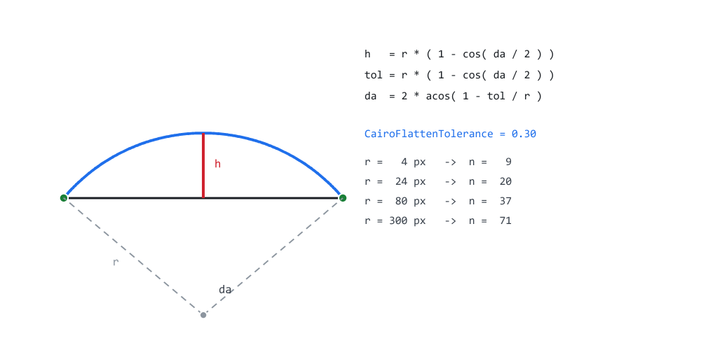
Figure 1. The bulge between a chord and its arc, and the formula from it.
Figure 1 has the geometry on the left and the consequence on the right. The blue curve is the true arc, the black line is the chord one segment would actually draw, and the red line between them is h — the entire error, in one measurable quantity. The two dashed radii meeting at the center span da, the angle the chord covers.
Here is the derivation as code, and it is the first of the two private helpers this part adds:
//+------------------------------------------------------------------+
//| StepForRadius - the angular step, in radians, that keeps an arc  |
//| within CairoFlattenTolerance of the true circle.                 |
//+------------------------------------------------------------------+
double CCairoPath::StepForRadius(const double r) const
  {
   double ratio = CairoFlattenTolerance / r;

//--- a tolerance larger than the radius means one segment is
//--- already more accurate than we asked for
   if(ratio > 1.0)
      ratio = 1.0;

   double step = 2.0 * MathArccos(1.0 - ratio);

//--- guard against a step so small the segment count explodes -
//--- this happens for an absurdly tiny tolerance on a huge radius
   if(step <= 1e-4)
      step = 0.25;

   return step;
  }
Both guards are there for a reason, and neither is hypothetical.
The ratio > 1.0 clamp covers a tolerance larger than the radius — a two-pixel dot drawn at a tolerance of six, which happens the moment somebody turns the quality down for a drag operation. It is worth being precise about what it protects against, because it is not only a NaN. MathArccos is defined on [−1, 1], so 1.0 - ratio stays valid all the way to a ratio of 2, and the NaN only begins beyond that. Between 1 and 2 the formula returns a step larger than π — one chord spanning more than half a turn — which is a valid number and a useless shape. The clamp caps the step at π instead, so it is a decision about shape as much as a guard against bad arithmetic. What a step of π then draws depends on the caller: AddCircle and AddEllipse lift two segments to their floor of eight, so the dot becomes an octagon, while a full turn through ArcTo gets two segments and collapses into a sliver with no area.
The step <= 1e-4 guard covers the other end: a huge radius with a microscopic tolerance produces an angular step so small that the segment count runs to millions. Falling back to a quarter-radian step is a deliberate refusal — it caps the work rather than letting one badly configured call stall the terminal. This is the same kind of protection as Part 6's depth cap of 18. It exists for the same reason: a caller-derived value can be arbitrarily large or small. The price should be stated plainly, though: the fallback does not keep the tolerance. A quarter-radian step on a large radius is a visibly coarser circle than was asked for, and nothing reports that to the caller. The comment on StepForRadius — a step that "keeps an arc within CairoFlattenTolerance" — holds for every step the formula produces, and not for this one.
Nor is the tolerance itself validated. Zero lands on that fallback; a negative value or a NaN produces a NaN step that neither guard catches. CairoFlattenTolerance is expected to be a positive number, and because it is a global, the vertices a shape receives depend on its value at the moment the shape is added rather than on anything stored in the path — which is why panel C of the demo saves it before changing it and restores it afterwards.
Look at what the formula produces at the default tolerance of 0.30 px, from the right-hand column of Figure 1. A 4-pixel radius gets 9 segments for a full circle. A 24-pixel radius gets 20. An 80-pixel radius gets 37, and a 300-pixel radius gets 71. Not one of those numbers was guessed, and none of them has to be maintained. A widget that is resized gets the segment count its new size deserves, for free, because the tolerance was expressed in pixels back in Part 6 rather than as a count.
Notice how slowly the count grows: the radius goes up by a factor of 75 from 4 px to 300 px, and the segment count goes up by a factor of 8. That is the square root relationship hiding in the cosine, and it is what makes this approach cheap at large sizes without giving up the tolerance.
That is the same principle as Part 6's adaptive flattening — let the work follow the difficulty — arrived at by formula instead of by recursion, and it is cheaper: one acos for the whole arc, against a recursion that evaluates a flatness test at every level of every branch. Recursion is not the only way to size a Bezier either — analytical bounds and precomputed tables exist — but none of them is as short as one acos, because none of them is working on a curve this regular.
ArcTo, and the vertex that is easy to lose
//+------------------------------------------------------------------+
//| ArcTo - a circular arc, appended as straight segments.           |
//+------------------------------------------------------------------+
void CCairoPath::ArcTo(const double cx, const double cy, const double r,
                       const double deg_from, const double deg_to)
  {
//--- a zero-radius corner is just the corner point itself. This is
//--- not an error case - it is how AddRoundRect draws a square
//--- corner without a special branch.
   if(r <= 0.0)
     {
      LineTo(cx, cy);
      return;
     }

   const double a0   = deg_from * M_PI / 180.0;
   const double a1   = deg_to   * M_PI / 180.0;
   const double step = StepForRadius(r);

   int n = (int)MathCeil(MathAbs(a1 - a0) / step);

   if(n < 1)
      n = 1;

   ReservePoints(m_point_count + n + 1);     // the count is known here

//--- THE START VERTEX. The loop below begins at i = 1, so it never
//--- emits the point at a0 - it assumes the pen is already there.
//--- That holds for AddRoundRect, where a LineTo has just walked
//--- the pen to the corner, and it is false everywhere else. A pie
//--- slice calling MoveTo( center ) then ArcTo() would silently
//--- lose its first vertex, so every wedge would start one segment
//--- late and the whole chart would appear rotated.
//---
//--- Three cases, which is what Cairo's own arc() does:
//---   no pen down       - the arc opens a new contour
//---   pen already at a0 - nothing to add
//---   pen somewhere else- join to the arc with a straight line
   const double sx = cx + r * MathCos(a0);
   const double sy = cy + r * MathSin(a0);

   if(!m_has_current)
      MoveTo(sx, sy);
   else
      if(MathAbs(m_cur_x - sx) > 1e-9 ||
         MathAbs(m_cur_y - sy) > 1e-9)
         LineTo(sx, sy);

   for(int i = 1; i <= n; i++)
     {
      const double a = a0 + (a1 - a0) * i / n;

      LineTo(cx + r * MathCos(a), cy + r * MathSin(a));
     }
  }
Unlike a Bezier, an arc knows its own vertex count before it emits anything — n is computed three lines above the loop. So this is one of the places where ReservePoints, added back in Part 5, earns its keep: one allocation of the right size, instead of the geometric regrowth AddPoint would otherwise perform as the loop runs. AddPolygon and AddPolyline already did this; arcs are the third caller, and every shape below goes through them.
Angles are in degrees, and 90 points down
The convention is the screen one, and it catches everybody once:
  0   points right  (+x)
 90   points DOWN   (+y)
180   points left
270   points up
It follows from y growing downward in this library's pixel buffer, which has been true since Part 1. Sine of 90° is +1, +1 in y is down, therefore 90° is down. Libraries that work in a y-down device space — Cairo, the HTML canvas, SVG — share the convention; an API with a y-up coordinate system, or its own angle rule, does not. The rule belongs to the coordinate system rather than to graphics in general, and it is still surprising the first time.
It is worth internalizing rather than looking up, because it makes the rounded-rectangle corners below read naturally instead of cryptically.
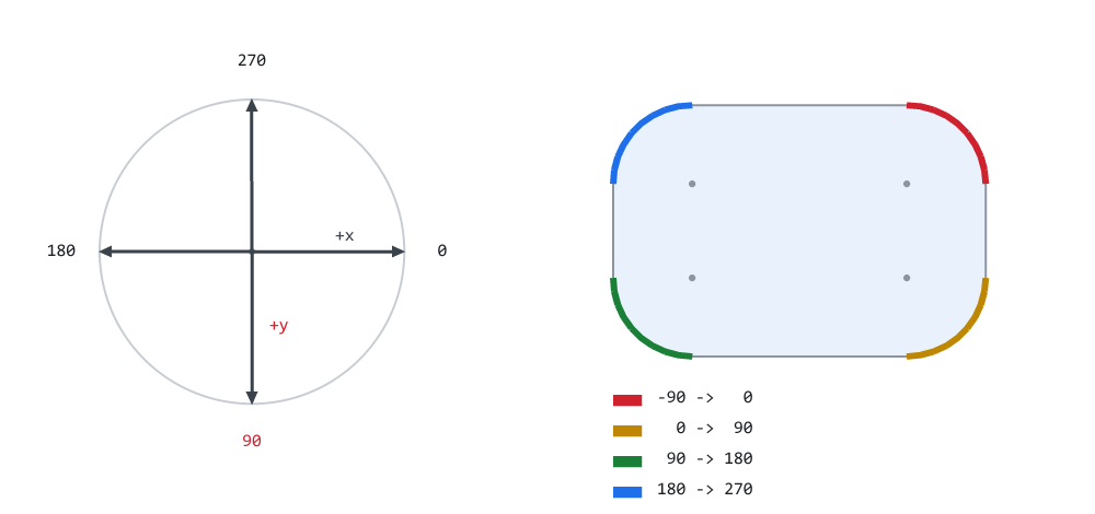
Figure 2. Zero points right and ninety points down, so -90 to 0 is top-right.
Figure 2 is the payoff. The compass on the left is the convention, with the +y arrow marked in red because that is the thing to remember. On the right, each corner of a rounded rectangle is drawn in the color of the sweep that produces it, and the legend lists those sweeps in the order AddRoundRect runs them: −90 → 0, then 0 → 90, then 90 → 180, then 180 → 270. Every pair increases, and every pair lands on the corner you would name.
The start vertex section is worth reading twice
The loop starts at i = 1, so it never emits the point at a0. It assumes the pen is already there.
That assumption is correct for AddRoundRect, where a LineTo has just walked the pen along a straight edge to the start of the corner. It is false almost everywhere else. A pie slice that calls MoveTo( center ) and then ArcTo() would silently lose the first vertex of the arc, and every wedge in the chart would start one segment late — which looks, at a glance, like the whole chart is very slightly rotated. That is a genuinely unpleasant bug to chase, because the picture is almost right.
So the three cases before the loop are not defensive padding; they are the function's contract:
- no pen down — the arc opens a new contour, so MoveTo;
- the pen is already at a0 — nothing to add, no duplicate vertex;
- the pen is somewhere else — join to the arc with a straight LineTo.
That join behavior is the one Cairo's arc() follows — with a current point it adds a line to the start of the arc, without one it begins a new sub-path — and matching it means code ported from a Cairo or SVG source joins its arcs the same way. The interfaces are not otherwise identical: ArcTo takes degrees rather than radians, sweeps backwards when deg_to is smaller than deg_from instead of needing a separate arc_negative(), and stores chords where Cairo stores Bezier segments.
The first test is on m_has_current, the pen flag, and not on the contour count. Those two are not interchangeable, and the difference is visible the moment a path holds more than one shape: after Close() the contour count is greater than zero but the pen has been lifted, so a test on the count would send the arc through the LineTo branch and draw a stray line from the previous shape's start point to the new arc. Testing the pen gives the right answer in both situations, and it is the same flag LineTo and CurveTo consult.
The 1e-9 comparison rather than == is the usual floating-point courtesy: the pen position arrived through trigonometry and will not land on a bit-identical value. The threshold is absolute rather than relative, which suits the pixel coordinates this library works in; at coordinates in the millions, or in fractions of a pixel, it would want to scale with them.
The zero-radius case is a feature
//--- a zero-radius corner is just the corner point itself. This is
//--- not an error case - it is how AddRoundRect draws a square
//--- corner without a special branch.
   if(r <= 0.0)
     {
      LineTo(cx, cy);
      return;
     }
A zero-radius corner is just the corner point. Writing that here, once, means AddRoundRect needs no branch for a square corner — it calls ArcTo with a radius of zero and gets a sharp corner out of the same code path that produces a round one. A tab rounded on top and square on the bottom is not a special case in any function; it is four numbers.
It also keeps StepForRadius safe. A radius of zero would make tol/r a division by zero, and this early return means that value never reaches it.
Rounded rectangles, one radius per corner
This is the most useful function in the library, and the reason is that a startling proportion of any interface is one call to it with different numbers:
card          r, r, r, r      all four rounded
tab           r, r, 0, 0      rounded on top only
pill / chip   h/2 everywhere  a capsule, via the clamp below
chat bubble   r, r, r, 0      one square corner points at the speaker
side panel    r, 0, 0, r      rounded on one side
ticket/badge  0, r, 0, r      notched diagonally
progress bar  h/2 everywhere  a track and a fill, same call twice
The corner order is top-left, top-right, bottom-right, bottom-left. This matches CSS border-radius. That is not a coincidence and not a preference: it means a design specification written by somebody who has never opened MetaEditor translates into a call without anyone rearranging arguments, and the argument order is one fewer source of errors in practice.
Only the order matches, though, and the difference matters for large radii. CSS resolves radii that do not fit by scaling all of them down together until each side's pair fits its length, so a wide box can keep large horizontal radii. This function clamps each radius on its own to half the shorter side, which is simpler and always safe, but rejects some shapes CSS would draw — a design that relies on CSS's scaling has to be translated, not copied. And the 0, r, 0, r row in the table alternates rounded and square corners diagonally; a ticket with real cut-out notches is a different shape, and it takes more than this call.
The function opens by settling the radii, and that half is worth reading on its own:
//+------------------------------------------------------------------+
//| AddRoundRect - a rectangle with an INDEPENDENT radius per corner.|
//+------------------------------------------------------------------+
void CCairoPath::AddRoundRect(const double x, const double y,
                              const double w, const double h,
                              const double r_tl, const double r_tr,
                              const double r_br, const double r_bl)
  {
   const double max_r = MathMin(w, h) * 0.5;

   double tl = r_tl, tr = r_tr, br = r_br, bl = r_bl;

//--- a negative radius is meaningless; treat it as square
   if(tl < 0.0)
      tl = 0.0;
   if(tr < 0.0)
      tr = 0.0;
   if(br < 0.0)
      br = 0.0;
   if(bl < 0.0)
      bl = 0.0;

   if(tl > max_r)
      tl = max_r;
   if(tr > max_r)
      tr = max_r;
   if(br > max_r)
      br = max_r;
   if(bl > max_r)
      bl = max_r;
Every radius is limited to half the shorter side. Without that, a radius larger than the box makes the corner arcs overshoot each other, the outline crosses itself, and the non-zero rule from Part 5 fills the result as a bow-tie — a shape that looks nothing like a rectangle and gives no clue what went wrong.
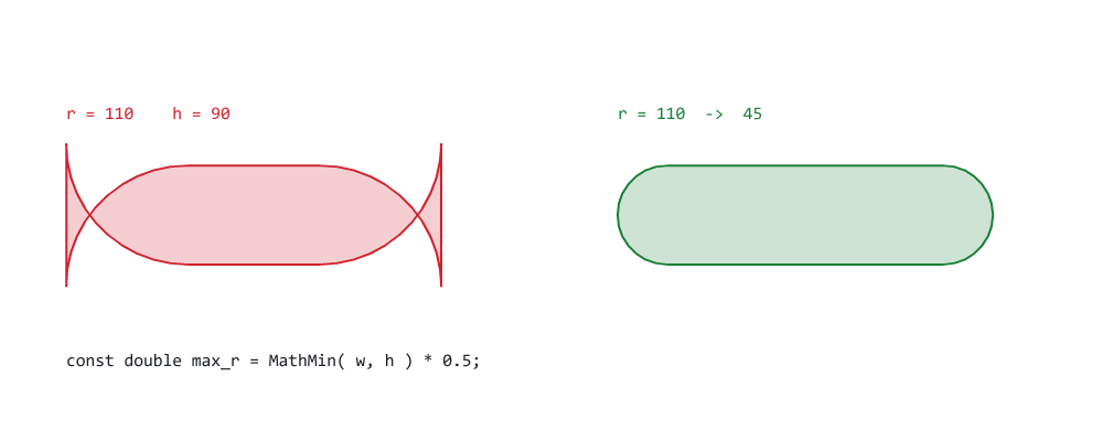
Figure 3. What an over-large radius fills without the clamp, and with it.
Figure 3 requires precision: neither panel is an illustration. Both were produced by building the outline AddRoundRect builds — with the clamp present on the right and removed on the left — and then filling it by running the non-zero winding rule over the result. The left panel is not a drawing of the bug. It is the bug, rendered by the same rule the engine uses. Look at what happened to the ends: the two corner arcs on each side have swept past each other and crossed, leaving those thin spikes standing outside the shape entirely.
And the clamp is not damage limitation. With it, an over-large radius degrades into a capsule, which is a genuinely useful shape, so:
//--- a pill, without having to know the height
pill.AddRoundRect( x, y, 120, 40, 999 );
Passing a deliberately absurd radius is the idiomatic way to ask for a pill. That matters more than it sounds in real code, where the height often is not a literal — it came from a layout calculation, a font metric, or a percentage of a parent — and 999 is a great deal more readable than threading h * 0.5 through three function calls.
The negative check above the clamp is a separate concern from it, and both are needed. A negative radius would sail past the > max_r test untouched and then be handed to ArcTo, whose r <= 0.0 branch would catch it — but only by accident, and only because that branch happens to exist. Normalizing to zero here says what was meant.
Neither check covers a negative width or height. Those make max_r negative, every radius is clamped below zero, ArcTo turns each corner into its corner point, and the result is a square-cornered rectangle mirrored across its origin — wound the other way when exactly one of the two is negative. w and h are expected to be positive, as they are in every call that comes from a layout.
Then the outline itself:
//--- Start just after the top-left corner, then walk the outline:
//--- straight edge, quarter arc, straight edge, quarter arc, and
//--- round. The winding direction matches AddRect and every other
//--- helper, for the reasons Part 5 demonstrated.
   MoveTo(x + tl, y);

   LineTo(x + w - tr, y);
   ArcTo(x + w - tr, y + tr, tr, -90.0, 0.0);           // top-right

   LineTo(x + w, y + h - br);
   ArcTo(x + w - br, y + h - br, br, 0.0, 90.0);        // bottom-right

   LineTo(x + bl, y + h);
   ArcTo(x + bl, y + h - bl, bl, 90.0, 180.0);          // bottom-left

   LineTo(x, y + tl);
   ArcTo(x + tl, y + tl, tl, 180.0, 270.0);             // top-left

   Close();
  }
Straight edge, quarter arc, straight edge, quarter arc, all the way round. It reads exactly like the shape, which is the whole argument for the angle convention: the sweep on each line is the corner named in the comment beside it, with nothing to work out.
Each ArcTo is centered on the corner's inset point, not on the corner of the box — x + w - tr, y + tr for the top-right, which is tr pixels in from both edges. That is the center of the circle the corner is a quarter of, and getting it wrong by using the box corner instead is the classic way to produce a rounded rectangle whose corners bulge outside its own bounds.
The winding direction matches AddRect and every other helper in the library, for the reasons Part 5 spent a whole section on. Rounded rectangles are going to get combined with each other constantly — a ring border is two of them in one path — and a helper that wound the other way would sabotage every one of those combinations.
The final Close() is doing real work here, which is a change from how this series used to describe it. Since Part 5 the path records whether each contour was closed, in m_closed[], and Close() also lifts the pen. Both matter: a rounded rectangle is unambiguously a closed shape, and lifting the pen means the next MoveTo, LineTo or ArcTo starts a fresh contour instead of running a line back from wherever this one ended.
Finally, the convenience overload, which is what almost every call site actually uses:
//+------------------------------------------------------------------+
//| The same radius on all four corners - the common case.           |
//+------------------------------------------------------------------+
void CCairoPath::AddRoundRect(const double x, const double y,
                              const double w, const double h,
                              const double r)
  {
   AddRoundRect(x, y, w, h, r, r, r, r);
  }
Note that there is no special case anywhere for a zero radius. ArcTo already treats r = 0 as "go to the corner point", so a square corner falls out of the same code path. Nine different corner combinations, one function, no branches.
Circles and ellipses
//+------------------------------------------------------------------+
//| AddEllipse.                                                      |
//+------------------------------------------------------------------+
void CCairoPath::AddEllipse(const double cx, const double cy,
                            const double rx, const double ry)
  {
   const double r    = MathMax(rx, ry);
   const double step = StepForRadius(r);

   int n = (int)MathCeil(2.0 * M_PI / step);

//--- never let a tiny ellipse collapse into a triangle: below
//--- about eight sides the eye reads it as a polygon, however
//--- correct the tolerance calculation was
   if(n < 8)
      n = 8;

   ReservePoints(m_point_count + n);          // the count is known here

   MoveTo(cx + rx, cy);

//--- stop at n-1: the final vertex would coincide with the first,
//--- and BuildEdges closes the contour for us anyway
   for(int i = 1; i < n; i++)
     {
      const double a = 2.0 * M_PI * i / n;

      LineTo(cx + rx * MathCos(a), cy + ry * MathSin(a));
     }

   Close();
  }
Three decisions in there.
The segment count comes from the larger radius. For an ellipse the curvature is not constant — the ends of the long axis are the tight parts — and the correct step varies as you go round. Sizing everything from MathMax( rx, ry ) is the conservative choice: it gives at least as many segments as the tightest part needs, everywhere. It costs a few redundant vertices along the flat sides of a very eccentric ellipse, and in exchange the function has no special cases and cannot under-sample. Note which way that error runs — it is the same direction Part 6's d1 + d2 test errs in, and for the same reason: shipping one extra segment is cheap, and shipping a visible facet is not. The vertices are also spaced evenly in the parametric angle, not by arc length or by curvature. On an eccentric ellipse that puts them closer together at the tight ends and further apart along the flat sides, which is roughly the right way round — but it is not the distribution the tolerance would choose, and some vertices do less work than others.
The floor of eight sides is not a tolerance calculation, and it is not covering for a bug. Below about eight sides the eye reads a shape as a polygon rather than as a small circle, however correct the arithmetic was — a six-pixel dot with five sides looks like a mistake even when it is inside tolerance. This is one of the places where 'what the number says' and 'what a person sees' come apart, and the code should side with the person. It is the one count in this part that is chosen rather than derived from the geometry.
The loop stops one vertex early. Emitting the vertex at 2π would place a duplicate on top of the vertex at 0. It would not change the rendered shape — BuildEdges would produce one zero-length edge, which fails the half-open crossing test from Part 3 and contributes nothing — but it would be a lie in PointCount(), and the demos in this series print PointCount() as evidence.
Unlike ArcTo, AddEllipse has no branch for a radius that is not positive. A zero radius produces eight vertices on the center — no area, nothing drawn — and a negative one hands StepForRadius a negative ratio and a NaN step, and the outcome then depends on how that NaN converts to a count. The policy for degenerate sizes is therefore not uniform: ArcTo and AddRoundRect normalize what they are given, while AddEllipse and AddCircle expect positive radii.
And then:
//+------------------------------------------------------------------+
//| AddCircle - an ellipse with equal radii.                         |
//+------------------------------------------------------------------+
void CCairoPath::AddCircle(const double cx, const double cy,
                           const double r)
  {
   AddEllipse(cx, cy, r, r);
  }
Four articles of demos have been faking circles with hand-computed polygons and a local AddNGon helper. It turns out the fake was the real thing all along: what the rasterizer receives for a circle is a polygon — the circle itself does not become one, but its stored representation does — and the only question ever worth asking was how many sides to give it. Part 3 made that point in passing; here it becomes the implementation.
That is every line this part adds: one private helper, one arc verb, and four shape helpers, all of them in Path.mqh.
Rings, gauges and donuts
None of these needs new library code, and that is the point of showing them.
A ring is Part 5's technique with circles in it — two contours in one path, filled even-odd:
      //--- the unfilled track
      CCairoPath track;
      track.AddCircle(cx, cy, 44);
      track.AddCircle(cx, cy, 34);
      Fill(track, C_LINE, CAIRO_EVENODD);
Two closed contours, one fill, and the inner disc is not painted rather than painted in the background color — which, as Part 5 showed with a checkerboard, is the difference between a border that works over anything and one that only works over what you expected.
A progress ring needs a partial band rather than a full ring, and the trick is worth having: sweep the outer radius forward through the value's angle, cut across to the inner radius, and sweep back:
      CCairoPath band;
      band.MoveTo(ox + 40 + r, oy + 220);
      band.ArcTo(ox + 40, oy + 220, r, 0.0, -90.0);
      band.LineTo(ox + 40, oy + 220 - (r - 8));
      band.ArcTo(ox + 40, oy + 220, r - 8, -90.0, 0.0);
      band.Close();
Out along the outer arc, across, back along the inner arc, close. One contour, filled non-zero, no stroker and no line width anywhere. The second ArcTo runs deg_to to deg_from — backwards — which is what makes the two arcs join into a band rather than crossing. That reversal is also why the explicit MoveTo on the first line is there: it puts the pen exactly on the start of the outer arc, so ArcTo takes its "pen already at a0" branch and the band opens cleanly.
Every segment of a donut chart is one call to that with a different angle range, and a gauge is the same thing with the range starting at −90 so that zero sits at twelve o'clock. Panel D of the demo draws three progress rings and a four-segment donut, all through it.
The demo
Demo07_RoundRect.mq5 is the widest demo in the series, because the point of this part is coverage rather than depth.
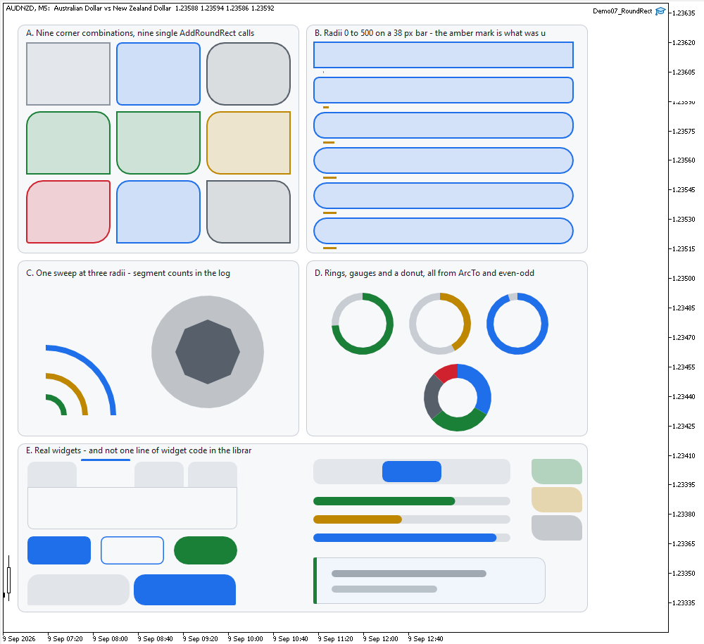
Figure 4. Demo07_RoundRect on a Black On White chart: five panels of shapes.
- A — the corner matrix: nine tiles, nine combinations of the four radii, each one a single AddRoundRect call.
//+------------------------------------------------------------------+
//| A. THE CORNER MATRIX                                             |
//+------------------------------------------------------------------+
void PanelCornerMatrix(const double ox, const double oy)
  {
   Card(ox, oy, 400, 325);

   double radii[9][4];

//--- row 1: the classics
   radii[0][0] =  0;
   radii[0][1] =  0;
   radii[0][2] =  0;
   radii[0][3] =  0;   // square
   radii[1][0] =  8;
   radii[1][1] =  8;
   radii[1][2] =  8;
   radii[1][3] =  8;   // card
   radii[2][0] = 26;
   radii[2][1] = 26;
   radii[2][2] = 26;
   radii[2][3] = 26;   // very round

//--- row 2: one side only
   radii[3][0] = 20;
   radii[3][1] = 20;
   radii[3][2] =  0;
   radii[3][3] =  0;   // tab
   radii[4][0] =  0;
   radii[4][1] =  0;
   radii[4][2] = 20;
   radii[4][3] = 20;   // bottom tab
   radii[5][0] = 20;
   radii[5][1] =  0;
   radii[5][2] =  0;
   radii[5][3] = 20;   // left cap

//--- row 3: asymmetric
   radii[6][0] = 24;
   radii[6][1] =  4;
   radii[6][2] = 24;
   radii[6][3] =  4;   // leaf
   radii[7][0] = 18;
   radii[7][1] = 18;
   radii[7][2] = 18;
   radii[7][3] =  0;   // chat bubble
   radii[8][0] =  0;
   radii[8][1] = 22;
   radii[8][2] =  0;
   radii[8][3] = 22;   // ticket

   uint cols[9];

   cols[0] = C_MUTED;
   cols[1] = C_BLUE;
   cols[2] = C_PURPLE;
   cols[3] = C_GREEN;
   cols[4] = C_GREEN;
   cols[5] = C_AMBER;
   cols[6] = C_RED;
   cols[7] = C_BLUE;
   cols[8] = C_PURPLE;

   const double tw = 120, th = 90, gap = 8;

   for(int i = 0; i < 9; i++)
     {
      const double tx = ox + 12 + (i % 3) * (tw + gap);
      const double ty = oy + 25 + (i / 3) * (th + gap);

      RoundRectBordered(tx, ty, tw, th,
                        radii[i][0], radii[i][1],
                        radii[i][2], radii[i][3],
                        CairoWithOpacity(cols[i], 0.18),
                        cols[i], 2.0);
     }
  }
- B — the clamp, with the radius that was actually used drawn as a marker under each bar. The bars are 38 pixels tall, so anything above 19 is clamped: the last three ask for 24, 40 and 500 and all three get 19.
//+------------------------------------------------------------------+
//| B. THE RADIUS CLAMP                                              |
//+------------------------------------------------------------------+
void PanelClamp(const double ox, const double oy)
  {
   Card(ox, oy, 400, 325);

   double asked[6] = { 0, 8, 16, 24, 40, 500 };

   for(int i = 0; i < 6; i++)
     {
      const double y = oy + 24 + i * 50;

      RoundRectBordered(ox + 10, y, 370, 38,
                        asked[i], asked[i], asked[i], asked[i],
                        CairoWithOpacity(C_BLUE, 0.16),
                        C_BLUE, 2.0);

      //--- the radius the clamp actually allowed
      const double used = MathMin(asked[i], MathMin(380.0, 38.0) * 0.5);

      CCairoPath bar;
      bar.AddRect(ox + 24, y + 42, MathMax(used, 1.0), 3);
      Fill(bar, C_AMBER);

      PrintFormat("B. asked for r = %5.0f  ->  used %5.1f", asked[i], used);
     }
  }
- C — arcs: one 90° sweep at three radii, with the vertex counts the sagitta formula produced printed to the log, plus a circle drawn again at a deliberately coarse tolerance so the facets are visible rather than theoretical.
//+------------------------------------------------------------------+
//| C. ARCS AND THE SAGITTA                                          |
//+------------------------------------------------------------------+
void PanelArcs(const double ox, const double oy)
  {
   Card(ox, oy, 400, 250);

   double radii[3] = { 30.0, 60.0, 100.0 };
   uint   cols[3];

   cols[0] = C_GREEN;
   cols[1] = C_AMBER;
   cols[2] = C_BLUE;

//--- three quarter-arcs sharing a center, drawn as bands
   for(int i = 0; i < 3; i++)
     {
      const double r = radii[i];

      CCairoPath band;
      band.MoveTo(ox + 40 + r, oy + 220);
      band.ArcTo(ox + 40, oy + 220, r, 0.0, -90.0);
      band.LineTo(ox + 40, oy + 220 - (r - 8));
      band.ArcTo(ox + 40, oy + 220, r - 8, -90.0, 0.0);
      band.Close();

      Fill(band, cols[i]);

      //--- how many vertices did the formula choose?
      CCairoPath probe;
      probe.MoveTo(ox + 40 + r, oy + 220);
      probe.ArcTo(ox + 40, oy + 220, r, 0.0, -90.0);

      PrintFormat("C. arc r = %5.1f px, 90 deg -> %d vertices",
                  r, probe.PointCount());
     }

//--- and a full circle, which is the same machinery closed up
   CCairoPath circ;
   circ.AddCircle(ox + 270, oy + 130, 80);
   Fill(circ, CairoWithOpacity(C_PURPLE, 0.35));

   PrintFormat("C. circle r = 80 px -> %d vertices", circ.PointCount());

//--- the same circle at a deliberately coarse tolerance, so the
//--- facets are visible and the setting is not just a number
   const double saved = CairoFlattenTolerance;
   CairoFlattenTolerance = 6.0;

   CCairoPath coarse;
   coarse.AddCircle(ox + 270, oy + 130, 46);
   Fill(coarse, C_PURPLE);

   PrintFormat("C. same circle at tolerance 6.0 px -> %d vertices "
               "(visibly faceted)",
               coarse.PointCount());

   CairoFlattenTolerance = saved;
  }
- D — rings, gauges and a donut, as above.
//+------------------------------------------------------------------+
//| D. RINGS, GAUGES AND A DONUT                                     |
//+------------------------------------------------------------------+
void ArcBand(const double cx, const double cy,
             const double r_out, const double r_in,
             const double deg_from, const double deg_to,
             const uint argb)
  {
   CCairoPath band;

   band.MoveTo(cx + r_out * MathCos(deg_from * M_PI / 180.0),
               cy + r_out * MathSin(deg_from * M_PI / 180.0));
   band.ArcTo(cx, cy, r_out, deg_from, deg_to);
   band.LineTo(cx + r_in * MathCos(deg_to * M_PI / 180.0),
               cy + r_in * MathSin(deg_to * M_PI / 180.0));
   band.ArcTo(cx, cy, r_in, deg_to, deg_from);
   band.Close();

   Fill(band, argb);
  }
- E — real widgets: tabs, buttons, a segmented control, progress bars, a toast, chat bubbles and badges.
//+------------------------------------------------------------------+
//| E. REAL WIDGETS FROM ONE PRIMITIVE                               |
//+------------------------------------------------------------------+
void PanelWidgets(const double ox, const double oy)
  {
   Card(ox, oy, 810, 240);


//--- Tabs: rounded on top only, the active one flush with the
//--- content area below it.

   const double tab_y = oy + 22;

   for(int i = 0; i < 4; i++)
     {
      const double tx     = ox + 14 + i * 76;
      const bool   active = (i == 1);

      CCairoPath tab;
      tab.AddRoundRect(tx, active ? tab_y : tab_y + 4, 70,
                       active ? 40 : 36, 10, 10, 0, 0);
      Fill(tab, active ? C_CARD
           : CairoWithOpacity(C_MUTED, 0.18));

      if(active)
        {
         CCairoPath stripe;
         stripe.AddRoundRect(tx, tab_y, 70, 3, 3, 3, 0, 0);
         Fill(stripe, C_BLUE);
        }
     }

//--- the content area the tabs sit on: square where they meet it
   RoundRectBordered(ox + 14, tab_y + 40, 298, 60, 0, 0, 8, 8,
                     C_CARD, C_LINE, 1.0);


//--- Buttons: filled, outlined, and pill-shaped.

   const double btn_y = tab_y + 110;

   CCairoPath primary;
   primary.AddRoundRect(ox + 14, btn_y, 90, 40, 8);
   Fill(primary, C_BLUE);

//--- an outlined button: no fill at all, so the card shows through
   RoundRectBordered(ox + 118, btn_y, 90, 40, 8, 8, 8, 8,
                     CAIRO_TRANSPARENT, C_BLUE, 1.5);

//--- a pill: radius clamped to half the height
   CCairoPath pill;
   pill.AddRoundRect(ox + 222, btn_y, 90, 40, 999);
   Fill(pill, C_GREEN);


//--- A segmented control and progress bars.

   const double seg_x = ox + 420;

   CCairoPath track;
   track.AddRoundRect(seg_x, tab_y, 280, 36, 10);
   Fill(track, CairoWithOpacity(C_MUTED, 0.18));

   CCairoPath sel;
   sel.AddRoundRect(seg_x + 98, tab_y + 3, 84, 30, 8);
   Fill(sel, C_BLUE);

   double progress[3] = { 0.72, 0.45, 0.93 };
   uint   pcols[3];

   pcols[0] = C_GREEN;
   pcols[1] = C_AMBER;
   pcols[2] = C_BLUE;

   for(int i = 0; i < 3; i++)
     {
      const double py = tab_y + 54 + i * 26;

      CCairoPath ptrack;
      ptrack.AddRoundRect(seg_x, py, 280, 12, 6);
      Fill(ptrack, CairoWithOpacity(C_MUTED, 0.25));

      CCairoPath pfill;
      pfill.AddRoundRect(seg_x, py, 280 * progress[i], 12, 6);
      Fill(pfill, pcols[i]);
     }


//--- A toast with an accent bar that shares the card's left radii,
//--- and two chat bubbles.

   const double tx2 = ox + 420;
   const double ty2 = tab_y + 140;

   RoundRectBordered(tx2, ty2, 330, 66, 0, 12, 12, 0,
                     CairoRgb(240, 246, 252), C_LINE, 1.0);

   CCairoPath accent;
   accent.AddRoundRect(tx2, ty2, 5, 66, 12, 0, 0, 12);
   Fill(accent, C_GREEN);

   for(int i = 0; i < 2; i++)
     {
      CCairoPath line;
      line.AddRoundRect(tx2 + 26, ty2 + 18 + i * 22,
                        220 - i * 70, 10, 5);
      Fill(line, CairoWithOpacity(C_MUTED, 0.8 - i * 0.25));
     }

//--- chat bubbles: three rounded corners, one square, and the
//--- square one points at whoever is speaking
   CCairoPath bubble_in;
   bubble_in.AddRoundRect(ox + 14, btn_y + 54, 145, 44, 16, 16, 16, 2);
   Fill(bubble_in, CairoWithOpacity(C_MUTED, 0.20));

   CCairoPath bubble_out;
   bubble_out.AddRoundRect(ox + 165, btn_y + 54, 145, 44, 16, 16, 2, 16);
   Fill(bubble_out, C_BLUE);

//--- badges with "ticket" corners
   for(int i = 0; i < 3; i++)
     {
      CCairoPath badge;
      badge.AddRoundRect(ox + 730, tab_y + i * 40, 72, 36,
                         4, 16, 4, 16);

      const uint bc = (i == 0) ? C_GREEN
                      : (i == 1) ? C_AMBER : C_PURPLE;

      Fill(badge, CairoWithOpacity(bc, 0.30));
     }
  }
The log is where panels B and C stop being decorative:
=== Part 7: arcs, circles and rounded rectangles ===
B. asked for r =     0  ->  used   0.0
B. asked for r =     8  ->  used   8.0
B. asked for r =    16  ->  used  16.0
B. asked for r =    24  ->  used  19.0
B. asked for r =    40  ->  used  19.0
B. asked for r =   500  ->  used  19.0
C. arc r =  30.0 px, 90 deg -> 7 vertices
C. arc r =  60.0 px, 90 deg -> 9 vertices
C. arc r = 100.0 px, 90 deg -> 12 vertices
C. circle r = 80 px -> 37 vertices
C. same circle at tolerance 6.0 px -> 8 vertices (visibly faceted)
The three sweeps in panel C are the same 90° of arc and get 7, 9 and 12 vertices — 6, 8 and 11 segments, since PointCount() includes the starting vertex — and all three look equally smooth on screen. That is the sagitta formula working: the largest arc gets not quite twice the vertices of the smallest despite being more than three times the radius, which is the square root relationship again.
The last two lines are the same machinery at two tolerances. At 0.30 px an 80-pixel circle is 37 vertices and reads as a circle; at 6.0 px a 46-pixel one falls to the 8-side floor and reads as an octagon. The difference on screen is what the tolerance actually means — not a number in a config file, but the distance at which you personally stop seeing corners. The log and the screenshots show the cases the demo chose; the degenerate ones — zero or negative sizes, extreme tolerances, very large coordinates — are covered by the rules stated above, not by anything on screen.
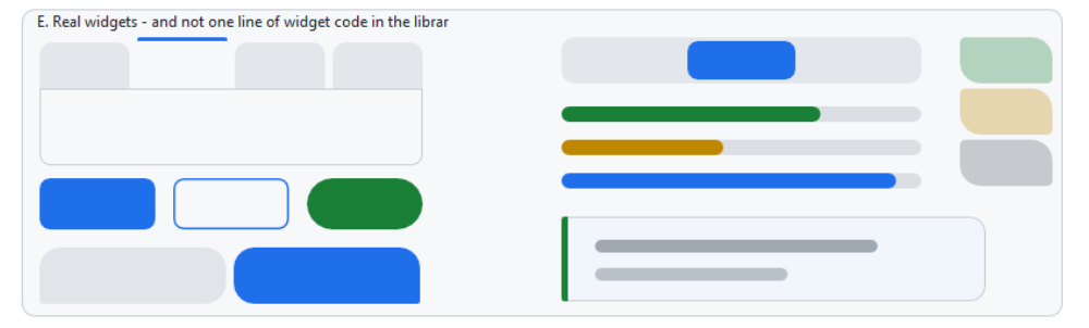
Figure 5. Panel E magnified: every widget here is one AddRoundRect call.
Panel E is the one that makes the argument of the whole series. There is no widget code in the library, and there never will be. A button is a rounded rectangle that somebody decided to call a button. A tab is a rounded rectangle with two of its radii set to zero. A pill is a rounded rectangle with a radius nobody bothered to compute. A segmented control is two of them side by side. A toast is one with a thin one on its left edge sharing its corner radii.
One structural note, and it is a happy one: this demo has noAddNGon helper. Parts 5 and 6 both needed one, and Part 6's vertex markers were squares because squares were all we had. Every circle here is AddCircle, and every marker is a dot.
Project structure
Extract the archive under MQL5/, preserve the folder structure, and compile Demo07_RoundRect.mq5. No paths need editing.
MQL5/
├── Include/
│   └── CairoG2D/
│       ├── Color.mqh          // the ARGB color type and blending
│       ├── Config.mqh         // CairoAaSamples, CairoFlattenTolerance
│       ├── Surface.mqh        // pixel buffer bound to one chart object
│       ├── Path.mqh           // the path and the edges, now + the arcs
│       ├── Raster.mqh         // the coverage fill and the fill rule
│       └── DemoTheme.mqh      // the demos' shared palette - NOT library code
└── Experts/
    └── CairoG2D/
        └── Article 07/
└── Demo07_RoundRect.mq5 // five panels of round shapes | # | File | Directory | Holds |
|---|---|---|---|
| 1 | Color.mqh | MQL5/Include/CairoG2D | the ARGB color type and CairoBlendOver |
| 2 | Config.mqh | MQL5/Include/CairoG2D | CairoAaSamples and CairoFlattenTolerance |
| 3 | Surface.mqh | MQL5/Include/CairoG2D | CCairoSurface - pixel buffer to chart bitmap |
| 4 | Path.mqh | MQL5/Include/CairoG2D | the path, the edges, the curves, and now the arcs |
| 5 | Raster.mqh | MQL5/Include/CairoG2D | CCairoRasterizer - coverage, compositing, fill rule |
| 6 | DemoTheme.mqh | MQL5/Include/CairoG2D | palette, chart setup, captions - not library code |
| 7 | Demo07_RoundRect.mq5 | MQL5/Experts/CairoG2D/Article 07 | five panels, from corners to widgets |
| 8 | Cairo-Style Library - Part 07.zip | archive containing all the attached files and their paths relative to the terminal's root folder. |
One file changed in this part, and it only gained new code. Path.mqh gained StepForRadius beside the flattener, ArcTo after the curve verbs, and the four shape helpers after AddPolyline, where the shape helpers live. Color.mqh, Config.mqh, Surface.mqh and Raster.mqh were not touched at all, and the attached include/ folder is exactly what the series has written so far — five files, and nothing from later parts.
The geometry layer is finished
Count what the path can describe now: points, lines, polygons, polylines, thick lines, cubic and quadratic Beziers, arcs, circles, ellipses, and rounded rectangles with an independent radius per corner. Combined with the two fill rules from Part 5, that is essentially everything a two-dimensional interface is made of.
One number matters more than the rest. Raster.mqh has not changed since Part 5, and BuildEdges has not changed since Part 3. Seven articles in, everything the library has learned to draw arrived as vertices in the same two arrays, and the code that turns vertices into pixels has never once needed to know what the vertices meant. That was the bet placed in Part 1, and it has now been paid out four times running. It holds for the job the rasterizer has, which is filling, and that is the job this design was chosen for. Strokes, dashes, hit tests and length measurements ask different questions, and some of them will want more than vertices.
What the engine cannot do is give a shape more than one flat color. Every fill in every demo has been a single ARGB value. Real interfaces are not flat: they have vertical gradients on buttons, radial glows behind focus rings, subtle sheens on cards, and heat-map ramps on data.
In Part 8 we fix that, and the shape of the fix should be predictable by now. We do not add a gradient case to the rasterizer. We introduce a paint source: an object that answers a single question—what color is this pixel? The solid color used so far becomes the simplest implementation. Linear and radial gradients become two more, and the rasterizer changes by about one line, because it stops being handed a color and starts being handed something it can ask.
That is the last structural piece. After Part 8 the engine is complete, and Parts 9 and 10 are about making the engine fast and building a widget toolkit on top of it.
The project is supported on MQL5 Algo Forge. Each part of this series has its own release, frozen at exactly the code that part explains, so whichever article you are reading, its release is the one to download.
Part 7 is here: https://forge.mql5.io/SandroBegashvil/CairoG2D/releases/tag/part-07
Warning: All rights to these materials are reserved by MetaQuotes Ltd. Copying or reprinting of these materials in whole or in part is prohibited.
This article was written by a user of the site and reflects their personal views. MetaQuotes Ltd is not responsible for the accuracy of the information presented, nor for any consequences resulting from the use of the solutions, strategies or recommendations described.


