

Creating a Cairo-Inspired Graphics Library for MetaTrader 5 (Part 2): Points, Contours and the Path
 528
528
 0
0

Contents
- Introduction
- What a path is, and what it is not
- The point, and why it must be a double
- Contours: one path, several outlines
- Storing contours: one flat array and an index
- Writing Path.mqh
- What we already have from Part 1
- The demo: seeing geometry we cannot yet fill
- What the demo shows
- Project structure
- Conclusion, and what is in Part 3
Introduction
Part 1 introduced Cairo's separation between what to draw and where it goes, then implemented the two supporting files: a color type Color.mqh and a surface that binds a pixel buffer to a single chart object Surface.mqh. We finished by writing pixels directly in nested loops and drawing a triangle and a circle with separate functions.
That demonstration exposed two limitations:
- the edges formed staircases because each pixel was either inside or outside, with no intermediate coverage;
- the approach does not scale because every new shape requires its own rendering function, loops, bounds, and edge handling.
This part addresses the second limitation by introducing a common representation for shape geometry. In Part 3, a single fill routine will use that representation without needing shape-specific rendering code. In this part, we implement Path.mqh. By the end, the library can describe geometry but cannot yet fill it.
This separation is deliberate. Filling is introduced in Part 3, after the geometry it consumes has been defined.
Here is the state of the library when we are done today:
Color.mqh      Part 1    the ARGB color type, uint 0xAARRGGBB
Surface.mqh    Part 1    a pixel buffer bound to one chart object
Path.mqh       Part 2    points, contours, MoveTo / LineTo / Close   <- today
What a path is, and what it is not
A path is a geometric description of one or more outlines. A path should not know its border thickness, color, or destination buffer. Mixing those responsibilities with geometry would require rendering features to be handled by shape-specific code.
So a path in this library has:
- no color
- no thickness
- no fill rule
- no pixels
It is a collection of points grouped into outlines. Rendering decisions are handled separately by code that operates on the resulting geometry. This follows the separation introduced in Part 1: rectangles, stars, circles, and glyphs can all be represented as geometric data and processed by the same rendering pipeline.
There is a second benefit, more practical and visible sooner: a path is cheap and reusable. It is a description, not a drawing, so it can be built once and then filled many times - in different colors, at different positions, under different fill rules - without re-computing any geometry. A dashboard that draws the same card outline in forty rows builds that outline once.
An analogy that holds all the way through the series: a path is sheet music, and the rasterizer is the instrument. The score says nothing about how loud, on what instrument, or in which room. That is why the same score can be played on a piano and an orchestra, and why the same path can be filled flat, filled with a gradient, or eventually stroked.
The point, and why it must be a double
Here is the entire type:
struct SCairoPoint
{
    double x;
    double y;
};
The point stores both coordinates as double values. The alternative is integer storage:
struct SCairoPoint    // NOT this
{
    int x;
    int y;
};
Integer coordinates would use less memory and may be slightly cheaper to process. Because screen pixels have integer positions, they may initially appear sufficient. CCanvas also uses integer coordinates, which limits the sub-pixel information available to a renderer.
To see why, take a rectangle whose left edge sits at x = 10.35. A pixel is not a point; it is a little square. Pixel column 10 covers the span from x = 10.0 to x = 11.0. If the shape begins at 10.35, then the part of column 10 that lies inside the shape runs from 10.35 to 11.0 - that is 0.65 of the column. The correct rendering is therefore:
column  9 :   0%   covered   ->  background
column 10 :  65%   covered   ->  65% of the way from background to shape color
column 11 : 100%   covered   ->  shape color
column 12 : 100%   covered   ->  shape color
Part 4 uses this same sub-pixel information to calculate coverage and produce anti-aliased edges.
The staircase in Part 1 resulted from the binary rendering approach and the loss of sub-pixel information.
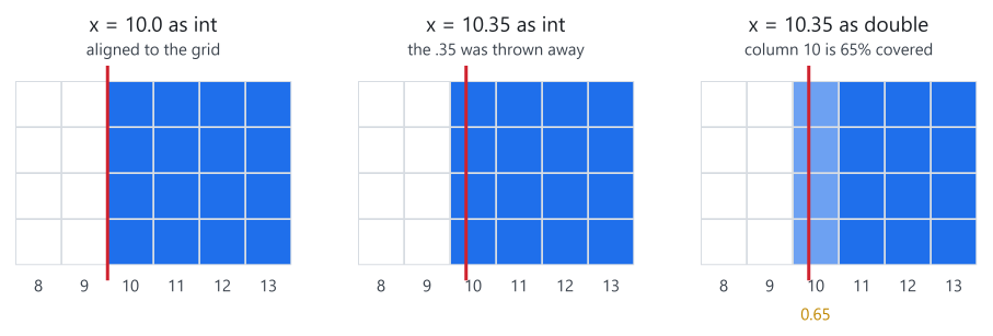
Figure 1. The same edge stored three ways: only the double keeps the 0.35.
In the first panel, the edge lies exactly on a pixel boundary, so integer storage loses no information. In the second, the original position is 10.35, but integer storage removes the fractional part. As a result, the renderer receives the same stored coordinate in both cases and cannot distinguish between them. The third panel preserves the coordinate as a double, allowing column 10 to retain its fractional coverage and the rendered edge to match the geometry.
This has two practical consequences:
- Quality. Anti-aliasing is built entirely out of these fractions. With integers there is nothing to anti-alias, because there is no fraction left to work with.
- Motion. A widget animating across a panel moves by fractions of a pixel per frame. With integer coordinates it can only jump from one whole pixel to the next, and the eye reads that as judder. With doubles it glides, because the boundary pixels change shade smoothly between whole-pixel steps.
Even a complex icon may contain thousands of points, while the geometry remains small compared with the pixel buffer used to render the panel.
Curves provide another reason to preserve floating-point coordinates. When a curve is flattened into straight segments, its vertices land at fractional positions (eg, 12.3719…, not 12). If the point type could not store those values, curves would be quantized to whole pixels before drawing, and anti-aliasing would not be able to compensate.
Contours: one path, several outlines
A path can hold more than one outline. Each separate outline is called a contour.
A contour is a sequence of vertices, and it can be open or closed. A closed contour is a shape with an inside: a rectangle, a glyph outline, a hole. An open contour is a line that starts somewhere and stops somewhere else: an indicator line, an equity curve. Both are valid paths, the path stores which one it holds, and the two are treated differently by later stages of the library.
Multiple contours support several common structures:
- the letter O - an outer outline and the hole inside it;
- a ring or a donut chart - two circles, one inside the other;
- a border - an outline plus an inset copy of itself;
- an icon - very often a dozen separate pieces;
- a multi-part indicator - several disconnected regions that must be filled with one color, in one operation.
These structures must be represented as a single path so that later fill rules can interpret the relationship between their contours correctly. The details are introduced in Part 5, but the required geometry model is defined here.
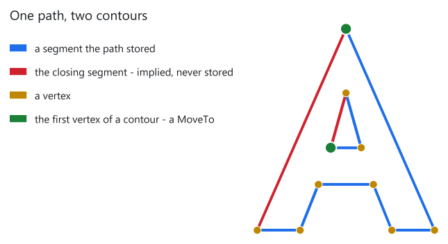
Figure 2. The letter A as one path: two contours and two implied closes.
Figure 2 enlarges case D from the demo. The two green markers indicate the first vertex of each contour. Each one is a MoveTo() call: one for the outside of the letter, one for the triangular counter in the middle. Everything else - the seven vertices of the outer outline and the three of the counter - arrived through LineTo().
Then look at the two red segments. Neither of them was ever stored. They are the segments that join each contour's last vertex back to its first. The path stores no vertex for them. What it stores is the fact that both contours were closed, and the section on Close() below explains why that fact is worth keeping.
The geometry remains unchanged across later stages. Part 3 fills both contours using the initial fill rule, while Part 5 can interpret the same geometry as a shape with a hole.
Storing contours: one flat array and an index
One possible design is an array of contour objects, each containing its own points. This implementation instead uses flat storage:
private:
    SCairoPoint m_points[];       // vertices of every contour, back to back
    int         m_point_count;
    int         m_starts[];       // index where each contour begins
    bool        m_closed[];       // did the author call Close() on contour c?
    int         m_contour_count;
One flat array holds the vertices of every contour, one after another, and a second, much smaller array records the index at which each contour begins.
A third array holds one bool per contour. It records whether that contour was closed. It is parallel to m_starts, so contour c has its start index in one array and its closed flag in the other. The section on Close() explains what the flag is for.
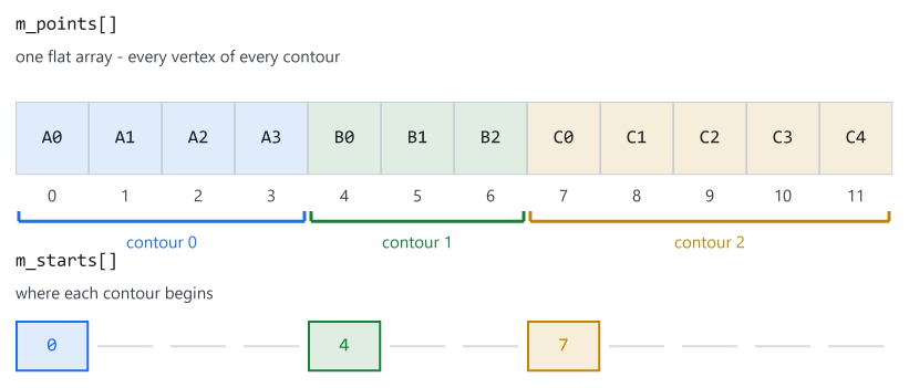
Figure 3. One flat vertex array, with m_starts marking where contours begin.
In Figure 3 the path holds three contours: a four-vertex one, a three-vertex one and a five-vertex one, twelve vertices in total. m_points holds all twelve in one run of memory. m_starts holds three numbers - 0, 4 and 7 - and each of them is drawn in the column of the vertex it points at, so the correspondence needs no arrows.
The rule for reading it is one line:
contour c runs from m_starts[c] up to m_starts[c + 1]
the last contour runs to m_point_count
This structure has three practical advantages:
Adding a contour requires only a start index. Flat storage also avoids maintaining a separate dynamic point array for each contour. Flat storage allows the rasterizer to traverse all vertices sequentially in contiguous memory. This matches the access pattern required when a path is processed repeatedly during rendering.
The library primarily needs two operations: walking the entire path and walking an individual contour. The only additional calculation is that a contour's length is derived from its start index and the beginning of the next contour.
A note on growing the arrays
This appears in AddPoint(), and it is easy to skim past:
if( ArraySize( m_points ) < i + 1 )
    if( ArrayResize( m_points, i + 1, 64 ) < i + 1 )
      {
       m_alloc_failed = true;
       return false;
      }
The third argument to ArrayResize() specifies a reserve, allowing subsequent appends to reuse pre-allocated space instead of resizing the array immediately. Without a reserve, repeated growth can trigger multiple reallocations and copies. The cost is negligible for small shapes but becomes more significant when curves are flattened into many vertices.
ArrayResize() is called only when the existing capacity is insufficient; otherwise, AddPoint() simply stores the new point and advances the count.
The return value is tested becauseArrayResize() can fail. If the array is not grown, writing tom_points[i] would go out of bounds. The failure is rare, but the symptom appears later: the path is consumed in another function and the panel renders incorrectly. So the point is refused instead, and the path remembers that something was refused.
The two numbers involved here are easy to confuse, so it is worth stating the rule once. m_point_count is the number of valid vertices. ArraySize() is the capacity, and it is usually larger, because the reserve leaves unwritten room at the end. Code that walks a path must use PointCount(), never ArraySize().
Writing Path.mqh
Everything below is the complete contents of Include/CairoG2D/Path.mqh, in order, with the file's own comment blocks trimmed so the code and the prose do not repeat each other. Nothing is left out.
The guard and the point#ifndef CAIRO5_PATH_MQH #define CAIRO5_PATH_MQH //+-------------------------------------------------------------------+ //| SCairoPoint - one vertex. | //+-------------------------------------------------------------------+ struct SCairoPoint { double x; double y; };
The include guard follows the naming convention established in Part 1 and prevents the header from being processed more than once. SCairoPoint is a plain data structure with public coordinates and no behavior.
The class declaration//+-------------------------------------------------------------------+ //| CCairoPath | //+-------------------------------------------------------------------+ class CCairoPath { private: //--- THE SIZE / CAPACITY INVARIANT. SCairoPoint m_points[]; // vertices of every contour, back to back int m_point_count; // valid vertices, NOT ArraySize( m_points ) int m_starts[]; // index into m_points where each contour begins bool m_closed[]; // did the author call Close() on contour c? int m_contour_count; // valid contours, NOT ArraySize( m_starts ) double m_cur_x; // the "pen" position double m_cur_y; bool m_has_current; // is there a pen position at all? bool m_alloc_failed; // sticky: some allocation was refused bool AddPoint(const double x, const double y); public: CCairoPath(); //----------------------------------------------------------------- // LIFECYCLE //----------------------------------------------------------------- void Clear(); void Release(); bool IsEmpty() const; //----------------------------------------------------------------- // HEALTH //----------------------------------------------------------------- bool IsValid() const { return !m_alloc_failed; } bool IsFinite() const; //--- capacity: ask for the room up front when the count is known bool ReservePoints(const int capacity); bool ReserveContours(const int capacity); //--- the primitive verbs void MoveTo(const double x, const double y); void LineTo(const double x, const double y); void Close(); //--- where is the pen right now, and is there one at all? double CurrentX() const { return m_cur_x; } double CurrentY() const { return m_cur_y; } bool HasCurrentPoint() const { return m_has_current; } //--- shape helpers: pure path construction, no rasterising void AddRect(const double x, const double y, const double w, const double h); void AddTriangle(const double x0, const double y0, const double x1, const double y1, const double x2, const double y2); void AddPolygon(const double &xs[], const double &ys[], const int n); void AddPolyline(const double &xs[], const double &ys[], const int n); //----------------------------------------------------------------- // INSPECTION //----------------------------------------------------------------- int PointCount() const { return m_point_count; } int ContourCount() const { return m_contour_count; } bool GetPoint(const int i, SCairoPoint &pt) const; bool GetContourInfo(const int c, int &start, int &length, bool &closed) const; bool IsContourClosed(const int c) const; double PointX(const int i) const { return m_points[i].x; } // unchecked double PointY(const int i) const { return m_points[i].y; } // unchecked int ContourStart(const int c) const; int ContourLength(const int c) const; };
Several design decisions are important here.
m_point_count tracks the number of stored vertices separately from the array capacity. Because reserved arrays can contain unused elements,ArraySize()does not represent the number of valid points. AddPoint()is private so that points can be added only through operations that maintain the contour structure. It returns bool, and the reason is explained with MoveTo() below. m_has_current records whether there is a pen position at all. Without it, the only way to answer that question is to look at the contour count, and that answer is wrong after a contour has been closed.
m_alloc_failed is sticky. Once an allocation is refused, the flag stays set until the path is cleared, and IsValid() reports it. This keeps the building code readable: the shape helpers call LineTo() many times and test nothing, and the caller asks one question at the end.
The class also offers two ways to read a vertex, and the difference is deliberate. GetPoint() and GetContourInfo() check the index and return false when it is out of range. PointX() and PointY() do not check anything. The rasterizer calls the second pair once per vertex per scanline and computes its own loop bounds, so the check would only cost time. Any other code should use the first pair.
Construction and reset//+------------------------------------------------------------------+ //| Constructor | //+------------------------------------------------------------------+ CCairoPath::CCairoPath() { Clear(); } //+-------------------------------------------------------------------+ //| Reset to an empty path - but KEEP the memory. | //+-------------------------------------------------------------------+ void CCairoPath::Clear() { m_point_count = 0; m_contour_count = 0; m_cur_x = 0.0; m_cur_y = 0.0; m_has_current = false; m_alloc_failed = false; } //+-------------------------------------------------------------------+ //| Clear, and hand the memory back to the terminal. | //+-------------------------------------------------------------------+ void CCairoPath::Release() { Clear(); ArrayResize(m_points, 0); ArrayResize(m_starts, 0); ArrayResize(m_closed, 0); } //+-------------------------------------------------------------------+ //| True when nothing has been added yet. | //+-------------------------------------------------------------------+ bool CCairoPath::IsEmpty() const { return (m_contour_count == 0); }
The constructor delegates to Clear(), so the empty state is defined in one place. The same reset operation can then be reused whenever a path is cleared.
Clear() sets the counts to zero and does not touch the arrays. Setting the counts to zero is the whole reset: any vertex past the count is unreachable, so there is nothing to erase. What stays is the memory the path was already given.
That matters for the way a panel is drawn. A dashboard that rebuilds its geometry on every tick clears the same path thousands of times an hour. If clearing also freed the arrays, the same memory would be released and requested again on every rebuild, to arrive at the same size it had a moment before. Keeping it means the first frame pays for the allocation and every frame after it does not.
Release() is the other half of the pair. It clears the path and gives the memory back. Use it when a path is really finished with - a one-off import, a cached shape being dropped. When it is not obvious which of the two is wanted, it is Clear().
IsEmpty() tests the contour count rather than the point count.
AddPoint: the pen itself//+-------------------------------------------------------------------+ //| Append a vertex and make it the current pen position. | //+-------------------------------------------------------------------+ bool CCairoPath::AddPoint(const double x, const double y) { const int i = m_point_count; if(ArraySize(m_points) < i + 1) if(ArrayResize(m_points, i + 1, 64) < i + 1) { m_alloc_failed = true; // out of memory - refuse, do not write return false; } m_points[i].x = x; m_points[i].y = y; m_point_count++; m_cur_x = x; m_cur_y = y; m_has_current = true; return true; }
The final two assignments update the current point.
The current point is used by LineTo() and later provides the implicit starting point required by curve operations.
This convention is also used by formats and APIs such as SVG, PostScript, and Cairo. Maintaining the current point therefore keeps the path model compatible with later curve operations and external path representations.
m_has_current is set here as well, because storing a vertex is exactly the moment a pen position starts to exist.
The function returns bool, and it has one caller that needs the answer. MoveTo() counts a contour before its first vertex is stored, so it has to undo that count if the vertex never arrives. Every other caller ignores the result and asks IsValid() at the end instead.
MoveTo: lift the pen//+-------------------------------------------------------------------+ //| MoveTo - begin a NEW contour at (x, y). | //+-------------------------------------------------------------------+ void CCairoPath::MoveTo(const double x, const double y) { const int c = m_contour_count; if(ArraySize(m_starts) < c + 1) if(ArrayResize(m_starts, c + 1, 16) < c + 1) { m_alloc_failed = true; return; } if(ArraySize(m_closed) < c + 1) if(ArrayResize(m_closed, c + 1, 16) < c + 1) { m_alloc_failed = true; return; } m_starts[c] = m_point_count; m_closed[c] = false; m_contour_count++; if(!AddPoint(x, y)) m_contour_count--; // <- the reason AddPoint returns bool: // never leave an empty contour behind }
MoveTo() begins a new contour, analogous to lifting a pen and placing it at a new position without drawing a connecting segment. Beginning a contour requires only recording the current point index and storing the first vertex. This is a direct consequence of the flat storage model.
The order matters: the start index must be recorded before AddPoint() increments m_point_count. Reversing the order would shift the contour boundary by one vertex.
The new contour is also marked as open. A contour is open until Close() says otherwise, and writing the flag here means it is never read before it is written.
The last two lines undo the contour if its first vertex could not be stored. Without them, a refused allocation would leave a contour of length zero in the middle of the path, and every loop that walks contours would have to know about it. The rule is simpler this way: a contour that exists has at least one vertex.
LineTo: drag the pen//+-------------------------------------------------------------------+ //| LineTo - straight segment from the pen to (x, y). | //+-------------------------------------------------------------------+ void CCairoPath::LineTo(const double x, const double y) { if(!m_has_current) MoveTo(x, y); else AddPoint(x, y); }
Normally, LineTo() appends a point to the current contour. If no contour exists, it creates one at the specified position.
Calling LineTo() on an empty path implicitly starts a new contour. This makes the API tolerant of a missing initial MoveTo(). Operationally, this library treats a closed contour as finished: the start coordinates are remembered, but there is no active current point for subsequent LineTo() calls.
The test is m_has_current and not the contour count, and the two are not the same question. After Close() the path has contours but no pen position, so a LineTo() that follows a Close() starts a new contour instead of adding a vertex to one the author already finished.
Close: recording the intent//+-------------------------------------------------------------------+ //| Close the current contour. | //+-------------------------------------------------------------------+ void CCairoPath::Close() { if(m_contour_count == 0) return; const int c = m_contour_count - 1; m_closed[c] = true; // record the intent - this is the whole point //--- Cairo semantics: the pen returns to where this contour began. //--- The contour is finished, so the next LineTo opens a new one. const int s = m_starts[c]; if(s < m_point_count) { m_cur_x = m_points[s].x; m_cur_y = m_points[s].y; } m_has_current = false; }
Close() stores no vertex, and it is worth being exact about that, because "stores no vertex" and "does nothing" are not the same statement.
The closing segment is never stored by anyone. When Part 3 converts contours into edges, it connects the final vertex back to the first automatically, for every contour, because a fill needs a boundary that closes. The red segments in Figure 2 are those edges. They are not in m_points and they do not need to be.
What Close() stores is the intention, and the fill rule cannot supply it. A polyline that happens to end where it started is not a closed contour. A triangle whose vertices are far apart is. Nothing in the vertex array separates those two cases, and the difference decides real behavior later: whether a stroke draws a joint or two end caps at that vertex, what an SVG exporter writes, what a hit test answers. Recovering the intention afterwards would mean guessing from the coordinates, and a guess is wrong occasionally.
So the contour is marked, and two things follow from that mark. Fill treats every contour as closed, because fill has no other option. Everything after fill can ask which contours the author closed, and get an answer that was recorded rather than inferred.
Following Cairo, the stored current coordinates are returned to the first vertex of the contour, but the pen is considered lifted: m_has_current becomes false, so the next LineTo() opens a new contour.The function also stays in the API for two reasons:
- It documents intent at the call site. AddRect() ending with Close() tells a reader that the outline is finished, and that the following MoveTo() is a new one.
- It matches Cairo. cairo_close_path exists, so code ported from a Cairo or SVG source reads identically, with no mental translation and no silent behavior change.
The distinction becomes important when strokes are introduced: open paths require end caps, while closed paths connect the final and first segments. The flag is what makes that decision possible, and it costs one bool per contour.
The shape helpersThe first shape helper is a rectangle:
//+-------------------------------------------------------------------+
//| Axis-aligned rectangle.                                           |
//+-------------------------------------------------------------------+
void CCairoPath::AddRect(const double x, const double y, const double w, const double h)
  {
   MoveTo(x,     y);
   LineTo(x + w, y);
   LineTo(x + w, y + h);
   LineTo(x,     y + h);
   Close();
  }
The helper only emits path vertices. The rendering stages receive the resulting geometry without needing rectangle-specific logic.
A triangle is the same idea with three points:
//+-------------------------------------------------------------------+
//| Triangle from three arbitrary points.                             |
//+-------------------------------------------------------------------+
void CCairoPath::AddTriangle(const double x0, const double y0,
                             const double x1, const double y1,
                             const double x2, const double y2)
  {
   MoveTo(x0, y0);
   LineTo(x1, y1);
   LineTo(x2, y2);
   Close();
  }
And then the general case:
//+-------------------------------------------------------------------+
//| Arbitrary CLOSED polygon from parallel x / y arrays.              |
//+-------------------------------------------------------------------+
void CCairoPath::AddPolygon(const double &xs[], const double &ys[], const int n)
  {
//--- a FILLED polygon needs area; use AddPolyline for open shapes
   if(n < 3)
      return;

   if(ArraySize(xs) < n || ArraySize(ys) < n)         // fewer points than promised
      return;

   ReservePoints(m_point_count + n);                  // the count is known: ask once

   MoveTo(xs[0], ys[0]);

   for(int i = 1; i < n; i++)
      LineTo(xs[i], ys[i]);

   Close();
  }

//+-------------------------------------------------------------------+
//| Arbitrary OPEN polyline from parallel x / y arrays.               |
//+-------------------------------------------------------------------+
void CCairoPath::AddPolyline(const double &xs[], const double &ys[], const int n)
  {
//--- one point is not a line
   if(n < 2)
      return;

   if(ArraySize(xs) < n || ArraySize(ys) < n)
      return;

   ReservePoints(m_point_count + n);

   MoveTo(xs[0], ys[0]);

   for(int i = 1; i < n; i++)
      LineTo(xs[i], ys[i]);

//--- deliberately no Close(): this contour stays open, and the path
//--- now remembers that instead of leaving it to be guessed
  }
Any shape that can be expressed as a sequence of vertices can be represented through AddPolygon() and processed by later rendering stages. Later circle support follows the same model: the circle is approximated by a sequence of vertices, while the rasterizer remains unchanged. Polygons with fewer than three vertices cannot enclose an area, so AddPolygon() ignores them. This prevents degenerate contours from reaching the fill stage.
That guard belongs to the helper, not to the path. A polygon is a shape with an inside, and two vertices enclose no inside, so there is nothing for this helper to build. It is not a rule that paths must be closed. AddPolyline() takes the same two arrays and stores the same vertices without closing them, and two vertices are enough for it, because a single segment is a legitimate path. An indicator line, an equity curve or the edge of a channel is that shape and not a polygon.
The two helpers differ in one line, and that line is the whole open-versus-closed distinction. Having both is what lets a caller state which one was meant, instead of the library deciding on their behalf.
Both also check the arrays they were given. If n is larger than the array, the loop would read past the end of the caller's data, and that mistake would happen inside the library. One comparison prevents it.
Both then call ReservePoints(). The vertex count is known before the first vertex is stored, so the room can be requested once instead of being grown into. The same method is worth calling directly whenever the count is known in advance - a flattened curve, a circle of ninety-six segments, a glyph outline. Note what it reserves: it raises the capacity without adding any vertex, so PointCount() does not change.
A note on vertex order
Every helper above walks its outline in a consistent rotational direction: AddRect() goes top-left, top-right, bottom-right, bottom-left, which is clockwise in screen coordinates where y increases downwards.
This ordering is an important convention because later fill rules read contour direction. Under the non-zero rule what matters is the relative direction of two contours: a hole must be wound against the outline that contains it. Emitting vertices in a stable order from every helper is what makes that relationship something the caller controls rather than discovers.
The library does not re-wind anything. AddPolygon() stores the order it is given, and a path built by hand keeps the order it was written in. The direction is the caller's decision, and Part 5 explains how to use it.
Reading a path back
The remaining methods expose contour boundaries and vertices for inspection:
//+-------------------------------------------------------------------+
//| Index of the first vertex of contour c.                           |
//+-------------------------------------------------------------------+
int CCairoPath::ContourStart(const int c) const
  {
   if(c < 0 || c >= m_contour_count)
      return 0;

   return m_starts[c];
  }

//+-------------------------------------------------------------------+
//| Number of vertices in contour c.                                  |
//+-------------------------------------------------------------------+
int CCairoPath::ContourLength(const int c) const
  {
   if(c < 0 || c >= m_contour_count)
      return 0;

   const int start = m_starts[c];
   const int end   = (c + 1 < m_contour_count) ? m_starts[c + 1] : m_point_count;

   return end - start;
  }
//+-------------------------------------------------------------------+
//| Ask for room for `capacity` vertices in total.                    |
//+-------------------------------------------------------------------+
bool CCairoPath::ReservePoints(const int capacity)
  {
   if(capacity <= ArraySize(m_points))
      return true;

   if(ArrayResize(m_points, capacity) < capacity)
     {
      m_alloc_failed = true;
      return false;
     }

   return true;
  }

//+-------------------------------------------------------------------+
//| The same, for the two per-contour arrays.                         |
//+-------------------------------------------------------------------+
bool CCairoPath::ReserveContours(const int capacity)
  {
   if(capacity <= ArraySize(m_starts) && capacity <= ArraySize(m_closed))
      return true;

   if(ArrayResize(m_starts, capacity) < capacity)
     {
      m_alloc_failed = true;
      return false;
     }

   if(ArrayResize(m_closed, capacity) < capacity)
     {
      m_alloc_failed = true;
      return false;
     }

   return true;
  }

//+-------------------------------------------------------------------+
//| Did the author call Close() on this contour?                      |
//+-------------------------------------------------------------------+
bool CCairoPath::IsContourClosed(const int c) const
  {
   if(c < 0 || c >= m_contour_count)
      return false;

   return m_closed[c];
  }

//+-------------------------------------------------------------------+
//| Read one vertex, safely.                                          |
//+-------------------------------------------------------------------+
bool CCairoPath::GetPoint(const int i, SCairoPoint &pt) const
  {
   if(i < 0 || i >= m_point_count)
      return false;

   pt = m_points[i];
   return true;
  }

//+-------------------------------------------------------------------+
//| Everything about one contour, in a single checked call.           |
//+-------------------------------------------------------------------+
bool CCairoPath::GetContourInfo(const int c, int &start, int &length, bool &closed) const
  {
   if(c < 0 || c >= m_contour_count)
      return false;

   start  = ContourStart(c);
   length = ContourLength(c);
   closed = m_closed[c];

   return true;
  }
ContourLength() derives the end of a contour from the next start index, or from m_point_count for the final contour. Both accessors return 0 for invalid indices, avoiding out-of-range array access. These accessors are intended for demos, tests, and debugging. The rasterizer can access the internal storage directly when processing every vertex.
That sounds like a minor convenience. It is not. In Part 6, when curves are flattened into straight segments, the fastest way to understand adaptive subdivision is to plot the vertices the flattener chose and watch them cluster where the curve bends hardest and thin out where it runs almost straight. These few accessors are what make that visible, and this article's demo is the first use of them.
GetContourInfo() answers the three questions a walk over a path needs - where a contour starts, how long it is, whether it was closed - with one range check. GetPoint() is the checked counterpart of PointX() and PointY(). It costs one comparison and it cannot go out of range, which is the right trade everywhere except the rasterizer's inner loop.
One more method belongs to this group, although it reads coordinates rather than structure:
//+-------------------------------------------------------------------+
//| Is every stored coordinate a real number?                         |
//+-------------------------------------------------------------------+
bool CCairoPath::IsFinite() const
  {
   for(int i = 0; i < m_point_count; i++)
      if(!MathIsValidNumber(m_points[i].x) ||
         !MathIsValidNumber(m_points[i].y))
         return false;

   return true;
  }

#endif // CAIRO5_PATH_MQH
Coordinates in a trading terminal are computed, not typed. They come out of indicator buffers, divisions and inputs, and any of those can produce NaN or an infinity. A path is not checked on every call, because that would put a test into the loop the rasterizer runs most often, to catch a mistake that belongs to the caller. So the rule is stated instead: coordinates are assumed to be finite, and IsFinite() is one linear pass that can be run on a finished path when the numbers came from somewhere uncertain.
It is worth using. A NaN found here is a bug with an address. The same NaN found by the rasterizer is a panel that is silently blank.
What we already have from Part 1
The demo reuses the files introduced in Part 1. The table summarizes the components required by this part:
| File | Written in | What this part uses from it |
|---|---|---|
| Include/CairoG2D/Color.mqh | Part 1 | CairoRgb, CairoArgb, the uint 0xAARRGGBB convention |
| Include/CairoG2D/Surface.mqh | Part 1 | CCairoSurface: Create, Clear, m_px, Flush, Destroy |
| Include/CairoG2D/DemoTheme.mqh | Part 1 | the light palette, DemoUseLightChart, DemoLabel |
Path.mqh is added without modifying the existing color or surface layers, demonstrating that the layers remain independent.
The demo: seeing geometry we cannot yet fill
It is a wireframe viewer used to inspect the stored geometry before the rasterizer is introduced.
The palette, and why these four colors//+-------------------------------------------------------------------+ //| THE WIREFRAME PALETTE. | //+-------------------------------------------------------------------+ #define C_GRID CairoRgb( 231, 235, 239 ) // the faint measuring grid #define C_EDGE DEMO_BLUE // a segment the path stored #define C_CLOSE DEMO_RED // the closing segment of a closed contour #define C_VERTEX DEMO_AMBER // every vertex #define C_START DEMO_GREEN // the first vertex of a contourFour colors come from the shared light theme, preserving the visual conventions used throughout the series.
Only the grid is defined locally. It has to be lighter than anything in the shared palette, because it sits behind the geometry and must not compete with it - a grid that draws attention to itself in a figure about outlines is a grid in the way.
Writing a pixel, and plotting a segment
SetPixel() is unchanged from Part 1 and is repeated here only because the plotting helpers stand on it:
//+-------------------------------------------------------------------+
//| Write one pixel (unchanged from Part 1).                          |
//+-------------------------------------------------------------------+
void SetPixel(const int x, const int y, const uint argb)
  {
   if(x < 0 || y < 0 || x >= g_surface.Width() || y >= g_surface.Height())
      return;

   g_surface.m_px[ y * g_surface.Width() + x ] = argb;
  }
And the plotter:
//+-------------------------------------------------------------------+
//| DEMO CODE, NOT LIBRARY CODE.                                      |
//+-------------------------------------------------------------------+
void PlotSegment(const double x0, const double y0,
                 const double x1, const double y1, const uint argb)
  {
   const double dx = x1 - x0;
   const double dy = y1 - y0;

//--- step once per pixel along the longer axis
   const int steps = (int)MathMax(MathAbs(dx), MathAbs(dy)) + 1;

   for(int i = 0; i <= steps; i++)
     {
      const double t = (double)i / steps;

      SetPixel((int)MathRound(x0 + dx * t),
               (int)MathRound(y0 + dy * t), argb);
     }
  }
The arithmetic is worth one paragraph, because the choice of steps is the only thought in it. Stepping along the longer axis guarantees that consecutive plotted pixels are at most one pixel apart, so the line comes out connected rather than dotted. Had we stepped a fixed number of times, a long line would have gaps and a short one would write the same pixel repeatedly.
PlotMarker() is even simpler - a small filled square, so a vertex can be seen:
//+-------------------------------------------------------------------+
//| DEMO CODE. A small filled square, to mark a vertex.               |
//+-------------------------------------------------------------------+
void PlotMarker(const double cx, const double cy, const int r, const uint argb)
  {
   for(int y = -r; y <= r; y++)
      for(int x = -r; x <= r; x++)
         SetPixel((int)MathRound(cx) + x,
                  (int)MathRound(cy) + y, argb);
  }
The function this article is really about
//+-------------------------------------------------------------------+
//| THE HEART OF THIS DEMO.                                           |
//+-------------------------------------------------------------------+
void PlotPath(CCairoPath &path)
  {
//--- two questions worth asking once, before drawing anything.
//--- A path that failed to allocate is short of vertices; a path
//--- carrying a NaN plots as a shape that silently is not there.
   if(!path.IsValid())
     {
      Print("PlotPath: incomplete path - an allocation was refused");
      return;
     }

   if(!path.IsFinite())
     {
      Print("PlotPath: the path holds a coordinate that is not a number");
      return;
     }

   int  start  = 0;
   int  count  = 0;
   bool closed = false;

   SCairoPoint a, b;

   for(int c = 0; c < path.ContourCount(); c++)
     {
      //--- where does this contour start, how long is it, was it closed
      if(!path.GetContourInfo(c, start, count, closed))
         continue;

      if(count < 2)
         continue;

      //--- the stored segments
      for(int i = 0; i < count - 1; i++)
         if(path.GetPoint(start + i, a) && path.GetPoint(start + i + 1, b))

            PlotSegment(a.x, a.y, b.x, b.y, C_EDGE);

      //--- the closing segment, drawn only because Close() was called
      if(closed)
         if(path.GetPoint(start + count - 1, a) && path.GetPoint(start, b))
            PlotSegment(a.x, a.y, b.x, b.y, C_CLOSE);

      //--- the vertices
      for(int i = 1; i < count; i++)
         if(path.GetPoint(start + i, a))
            PlotMarker(a.x, a.y, 2, C_VERTEX);

      //--- and where this contour began
      if(path.GetPoint(start, a))
         PlotMarker(a.x, a.y, 3, C_START);
     }
  }

//+-------------------------------------------------------------------+
//| A faint background grid, so positions can be judged by eye.       |
//+-------------------------------------------------------------------+
void PlotGrid(const int step)
  {
   for(int x = 0; x < g_surface.Width(); x += step)
      for(int y = 0; y < g_surface.Height(); y++)
         SetPixel(x, y, C_GRID);

   for(int y = 0; y < g_surface.Height(); y += step)
      for(int x = 0; x < g_surface.Width(); x++)
         SetPixel(x, y, C_GRID);
  }
PlotPath() operates only on contours and vertices. This demonstrates the central advantage of the path representation: the processing code is independent of individual shape types.
The count < 2 guard skips a contour with a single vertex, which cannot produce a segment.
The red closing segment is drawn when the contour says it is closed. Nothing tells this function which cases are open shapes; it reads the flag and follows it. That is the point of storing the flag, and the demo would need a switch of its own without it.
The two checks at the top are cheap and they are the only place where a broken path can still be reported. An incomplete path draws a shape that is quietly missing vertices; a path holding a NaN draws nothing at all and explains nothing.
Every index in this function could be handed to PointX() and PointY() instead, and all of them would be in range. It uses the checked accessors anyway, because that is the right habit for code that receives a path it did not build. The rasterizer in Part 3 will use the fast pair, and it may: it computes its own loop bounds. When writing tools on top of a path, this function is the one to copy.
The seven cases
Each case builds a path, plots it, and prints what it contains. Case A is the smallest possible example:
//+-------------------------------------------------------------------+
//| A. THE SIMPLEST PATH                                              |
//+-------------------------------------------------------------------+
void CaseRect(const double ox, const double oy)
  {
   CCairoPath p;
   p.AddRect(ox, oy, 170, 110);

   PlotPath(p);

   PrintFormat("A. rectangle       : %d contour(s), %d vertices",
               p.ContourCount(), p.PointCount());

//--- what Close() left behind: the pen is back at the first vertex,
//--- and it is lifted, so the next LineTo would open a new contour
   PrintFormat("     after Close(): pen at %.1f, %.1f  pen down = %s",
               p.CurrentX(), p.CurrentY(),
               p.HasCurrentPoint() ? "true" : "false");
  }
The rectangle contains four vertices. Three segments are stored explicitly, while the fourth closing segment is implied.
The second line of output shows what Close() left behind: the pen is back at the first vertex, and it is lifted. This is the state a following LineTo() would see, and it is why that call would begin a new contour.
Case B computes ten vertices and hands them over as an anonymous list:
//+-------------------------------------------------------------------+
//| B. AN ARBITRARY POLYGON                                           |
//+-------------------------------------------------------------------+
void CaseStar(const double ox, const double oy)
  {
   double xs[10], ys[10];

   for(int i = 0; i < 10; i++)
     {
      const double r = (i % 2 == 0) ? 68.0 : 28.0;
      const double a = -M_PI * 0.5 + M_PI * i / 5.0;

      xs[i] = ox + 85 + r * MathCos(a);
      ys[i] = oy + 75 + r * MathSin(a);
     }

   CCairoPath p;
   p.AddPolygon(xs, ys, 10);

   PlotPath(p);

   PrintFormat("B. star            : %d contour(s), %d vertices",
               p.ContourCount(), p.PointCount());
  }
The star is constructed from ten computed vertices. The path receives only those coordinates and does not need to know how they were generated.
Case C demonstrates how one path can contain multiple contours:
//+-------------------------------------------------------------------+
//| C. TWO CONTOURS IN ONE PATH                                       |
//+-------------------------------------------------------------------+
void CaseTwoContours(const double ox, const double oy)
  {
   CCairoPath p;

//--- two contours, eight vertices, and we know it before we start
   p.ReserveContours(2);
   p.ReservePoints(8);

   p.AddRect(ox,      oy,      190, 130);
   p.AddRect(ox + 22, oy + 22, 146,  86);

   PlotPath(p);

   PrintFormat("C. frame           : %d contour(s), %d vertices"
               "  <- one path, two outlines",
               p.ContourCount(), p.PointCount());

   for(int c = 0; c < p.ContourCount(); c++)
      PrintFormat("     contour %d: starts at index %d, %d vertices, closed = %s",
                  c, p.ContourStart(c), p.ContourLength(c),
                  p.IsContourClosed(c) ? "true" : "false");
  }
Two AddRect() calls on one path object. Because each helper begins with a MoveTo(), the second rectangle does not continue the first - it starts a new contour, and the path now holds two outlines and eight vertices. The extra loop prints the start index, the length and the closed flag of each, which is the storage model from Figure 3 made visible at runtime.
The two reservations at the top are not required. Two rectangles are eight vertices, and the count is known before the first one is added, so the case asks for the room once. On a path this small the saving is nothing; the habit is what matters, because the same two lines in front of a flattened curve save several reallocations.
Case D is the glyph from Figure 2, built by hand so that the two MoveTo() calls are explicit in the source:
//+-------------------------------------------------------------------+
//| D. A MULTI-PART GLYPH                                             |
//+-------------------------------------------------------------------+
void CaseGlyph(const double ox, const double oy)
  {
   CCairoPath p;

//--- outer outline
   p.MoveTo(ox +  70, oy +   8);
   p.LineTo(ox + 128, oy + 140);
   p.LineTo(ox + 100, oy + 140);
   p.LineTo(ox +  88, oy + 110);
   p.LineTo(ox +  52, oy + 110);
   p.LineTo(ox +  40, oy + 140);
   p.LineTo(ox +  12, oy + 140);
   p.Close();

//--- the counter - the hole in the middle of the A
   p.MoveTo(ox +  60, oy +  86);
   p.LineTo(ox +  80, oy +  86);
   p.LineTo(ox +  70, oy +  50);
   p.Close();

   PlotPath(p);

   PrintFormat("D. glyph 'A'       : %d contour(s), %d vertices",
               p.ContourCount(), p.PointCount());
  }
A font glyph is exactly this and nothing more: a set of contours, some of which are holes. TrueType adds curves, which Part 6 gives us, and a rule for deciding which contours are holes, which Part 5 gives us. The storage does not change.
Case E is the demonstration that the fractions are really being kept:
//+-------------------------------------------------------------------+
//| E. SUB-PIXEL COORDINATES ARE REAL                                 |
//+-------------------------------------------------------------------+
void CaseSubPixel(const double ox, const double oy)
  {
   Print("E. sub-pixel offsets stored in the path:");

   CCairoPath p;

   for(int i = 0; i < 6; i++)
     {
      const double x = ox + i * 40 + i / 6.0;

      p.Clear();                      // reset the geometry, keep the memory
      p.AddRect(x, oy, 26, 90);

      PlotPath(p);

      //--- index 0 is the vertex AddRect just wrote, so the fast
      //--- unchecked accessor is safe here by construction
      PrintFormat("     rect %d: x = %.4f  (plotted at pixel column %d)",
                  i, p.PointX(0), (int)MathRound(p.PointX(0)));
     }

   p.Release();                        // done with it - hand the memory back
  }
Six rectangles are offset by successive fractions of a pixel. The stored coordinates preserve those offsets, while the demonstration plotter rounds them to whole pixel columns. This difference illustrates why Part 4 introduces coverage-based rasterization.
This case also shows how a path is meant to be reused. One path object is built six times. Clear() empties it without returning the memory, so the first rectangle pays for the allocation and the other five do not. An expert that redraws on every tick should be written this way. Release() at the end is correct only because this path is genuinely finished with.
Case F closes the set by showing what a path is when nobody intends to fill it:
//+-------------------------------------------------------------------+
//| F. AN OPEN CONTOUR                                                |
//+-------------------------------------------------------------------+
void CaseOpenPolyline(const double ox, const double oy)
  {
   CCairoPath wave;
   wave.ReservePoints(23);            // we know the count in advance

   wave.MoveTo(ox, oy);

   for(int i = 1; i <= 22; i++)
      wave.LineTo(ox + i * 11, oy + MathSin(i * 0.55) * 52);

//--- no Close() here, deliberately

   PlotPath(wave);

   PrintFormat("F. open polyline   : %d contour(s), %d vertices, closed = %s",
               wave.ContourCount(), wave.PointCount(),
               wave.IsContourClosed(0) ? "true" : "false");
  }
A path can also represent an open polyline. Close() is simply never called, and the path records that: no red segment appears, and nothing in the demo had to be told to leave it out. Compare it with case A, where four vertices and one Close() produce a fifth side that was never stored. Every price series drawn as a line is this shape.
Case G puts the two side by side:
//+-------------------------------------------------------------------+
//| G. THE SAME VERTICES, TWO WAYS                                    |
//+-------------------------------------------------------------------+
void CasePolylineVsPolygon(const double ox, const double oy)
  {
   double xs[5], ys[5];

   for(int i = 0; i < 5; i++)
     {
      xs[i] = ox + i * 55;
      ys[i] = oy + ((i % 2 == 0) ? -34.0 : 0.0);
     }

   CCairoPath p;
   p.ReserveContours(2);
   p.ReservePoints(10);

//--- open: the vertices, and nothing else
   p.AddPolyline(xs, ys, 5);

//--- the same five vertices, shifted down and closed this time
   for(int i = 0; i < 5; i++)
      ys[i] += 90.0;

   p.AddPolygon(xs, ys, 5);

   PlotPath(p);

   int  start, count;
   bool closed;

   PrintFormat("G. polyline+polygon: %d contour(s), %d vertices",
               p.ContourCount(), p.PointCount());

   for(int c = 0; c < p.ContourCount(); c++)
      if(p.GetContourInfo(c, start, count, closed))
         PrintFormat("     contour %d: %d vertices from index %d, closed = %s  <- %s",
                     c, count, start, closed ? "true" : "false",
                     closed ? "AddPolygon" : "AddPolyline");
  }
The same five vertices are handed to both helpers. The upper zig-zag comes from AddPolyline() and has no red segment. The lower one comes from AddPolygon() and closes across the bottom. They live in one path, and the difference between them is one call inside the library.
This is the open-versus-closed distinction in a single picture. Nothing about the coordinates says which is which. The path knows because the caller said so.
Composing the frame//+-------------------------------------------------------------------+ //| Compose the frame. | //| | //| Every call below writes into memory. Exactly one line - the final | //| Flush - touches the terminal. | //+-------------------------------------------------------------------+ void Render() { g_surface.Clear(DEMO_BG); PlotGrid(20); Print("=== Part 2: paths built, nothing filled ==="); CaseRect(40, 46); CaseStar(260, 46); CaseTwoContours(470, 40); CaseGlyph(700, 30); CaseSubPixel(40, 246); CaseOpenPolyline(320, 430); CasePolylineVsPolygon(600, 420); g_surface.Flush(); }
The demo follows the rendering structure established in Part 1: drawing operations modify the pixel buffer, and a single Flush() updates the chart object.
OnInit() puts the chart into the Black On White scheme, creates the surface, renders, and adds the captions:
//+-------------------------------------------------------------------+
//| Expert initialization function                                    |
//+-------------------------------------------------------------------+
int OnInit()
  {
   if(InpSetLightChart)
      DemoUseLightChart();

   if(!g_surface.Create("cairo_demo02", UI_X, UI_Y, UI_W, UI_H))
     {
      Print("Cairo5: failed to create the surface");
      return INIT_FAILED;
     }

   Render();

   if(InpShowCaptions)
      Captions();

   ChartRedraw();

   return INIT_SUCCEEDED;
  }
The captions use OBJ_LABEL objects because the library does not yet include a text renderer. They serve only as annotations and can be disabled.
What the demo shows
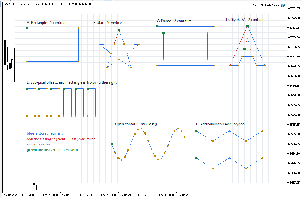
Figure 4. Demo02_PathViewer on a Black On White chart, showing seven cases.
Figure 4 shows the complete path viewer running on a MetaTrader chart. The marker colors distinguish stored segments, closing segments, vertices, and contour starts. A red segment appears only where a contour was closed, so the open cases are visibly open.
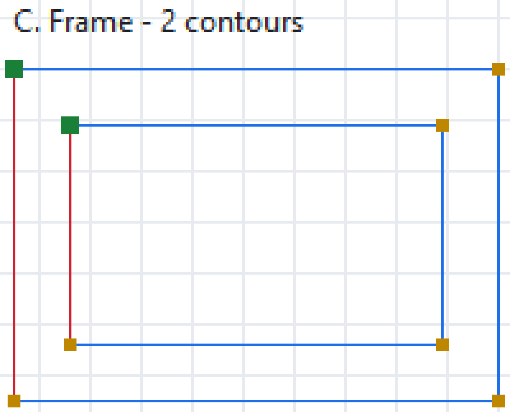
Figure 5. Case C enlarged: two green markers, so two MoveTo() calls, one path.
Figure 5 enlarges the multi-contour example: one path contains two contours and eight vertices.
The log exposes the stored contour structure:
=== Part 2: paths built, nothing filled ===
A. rectangle       : 1 contour(s), 4 vertices
     after Close(): pen at 40.0, 46.0  pen down = false
B. star            : 1 contour(s), 10 vertices
C. frame           : 2 contour(s), 8 vertices  <- one path, two outlines
     contour 0: starts at index 0, 4 vertices, closed = true
     contour 1: starts at index 4, 4 vertices, closed = true
D. glyph 'A'       : 2 contour(s), 10 vertices
E. sub-pixel offsets stored in the path:
     rect 0: x = 40.0000  (plotted at pixel column 40)
     rect 1: x = 80.1667  (plotted at pixel column 80)
     rect 2: x = 120.3333  (plotted at pixel column 120)
     rect 3: x = 160.5000  (plotted at pixel column 161)
     rect 4: x = 200.6667  (plotted at pixel column 201)
     rect 5: x = 240.8333  (plotted at pixel column 241)
F. open polyline   : 1 contour(s), 23 vertices, closed = false
G. polyline+polygon: 2 contour(s), 10 vertices
     contour 0: 5 vertices from index 0, closed = false  <- AddPolyline
     contour 1: 5 vertices from index 5, closed = true  <- AddPolygon
Three parts of the output illustrate the main storage and precision properties:
Case C's two contour lines are Figure 3 at runtime: contour 0 starts at index 0 and holds four vertices, contour 1 starts at index 4 and holds four. One m_points array, one m_starts array, and the boundary between two outlines expressed as a single integer.
The rounding occurs only in the demonstration plotter; the path itself preserves the original fractional coordinates.
Case G's two contour lines are the same five vertices reported twice. The counts match, the start indices follow one another, and the only field that differs is the closed flag. That single field is what the rest of the library will read when it needs to know whether a shape has an edge that joins back or two ends that stop.
Project structure
The attached archive contains the complete source for this part. Extract it under MQL5/, preserve the folder structure, and compile Demo02_PathViewer.mq5.
MQL5/
├── Include/
│   └── CairoG2D/
│       ├── Color.mqh          // the ARGB color type
│       ├── Surface.mqh        // pixel buffer bound to one chart object
│       ├── Path.mqh           // points, contours, the path
│       └── DemoTheme.mqh      // the demos' shared palette - NOT library code
└── Experts/
    └── CairoG2D/
        └── Article 02/
            └── Demo02_PathViewer.mq5  // the demo - builds paths, plots what they say
From this part onward, library headers are stored under MQL5/Include/CairoG2D/, and the demos sit under MQL5/Experts/CairoG2D/. This structure remains unchanged in later parts.
| # | File | Directory | What it holds |
|---|---|---|---|
| 1 | Color.mqh | MQL5/Include/CairoG2D | the ARGB color type, constructors, interpolation |
| 2 | Surface.mqh | MQL5/Include/CairoG2D | CCairoSurface - pixel buffer to chart bitmap |
| 3 | Path.mqh | MQL5/Include/CairoG2D | SCairoPoint, CCairoPath, contours |
| 4 | DemoTheme.mqh | MQL5/Include/CairoG2D | palette, chart setup, captions - not library code |
| 5 | Demo02_PathViewer.mq5 | MQL5/Experts/CairoG2D/Article 02/ | the demo - builds paths, plots what they say |
| 6 | Cairo Style Library - Part 02.zip | archive containing all the attached files and their paths relative to the terminal's root folder. |
Conclusion, and what is in Part 3
Part 2 adds the geometry layer required by the renderer:
- double coordinates for preserving sub-pixel geometry;
- contours for representing multiple outlines within one path;
- flat storage with contour start indices;
- MoveTo(), LineTo(), and Close() for constructing straight-segment paths;
- a closed flag per contour, so an open polyline and a closed shape are different things in storage and not only on screen;
- shape helpers that convert higher-level shapes into the same path representation.
The central result is that different shapes now produce the same path representation. Processing code can therefore operate on the geometry without requiring shape-specific logic.
Part 3 uses this geometry representation to introduce rasterization. We introduce the edge - a segment pre-processed for scanline queries, with its endpoints sorted by y and its slope computed once - and write BuildEdges(), which converts contours into edges and closes every contour automatically along the way, so the closing segments that no path ever stores are finally drawn. The first rasterizer uses scanlines to convert path edges into filled regions.
The rasterizer will fill any geometry represented by the path model, using the same processing pipeline for every shape. The first version will still produce hard edges; coverage-based anti-aliasing follows in Part 4.
Part 3 is where the paths first become filled shapes.
The project is supported on MQL5 Algo Forge. Each part of this series has its own release, frozen at exactly the code that part explains, so whichever article you are reading, its release is the one to download.
Part 2 is here: https://forge.mql5.io/SandroBegashvil/CairoG2D/releases/tag/part-02
Warning: All rights to these materials are reserved by MetaQuotes Ltd. Copying or reprinting of these materials in whole or in part is prohibited.
This article was written by a user of the site and reflects their personal views. MetaQuotes Ltd is not responsible for the accuracy of the information presented, nor for any consequences resulting from the use of the solutions, strategies or recommendations described.

 The Mathematics of Volatility: Why the GRI Indicator Deserves to Return to Your Trading Terminal
 Market Simulation: Position View (XIV)
 Ebola Optimization Search Algorithm (EOSA)
 From Basic to Intermediate: Classes (I)

- Free trading apps
- Over 8,000 signals for copying
- Economic news for exploring financial markets
You agree to website policy and terms of use