

Creating a Cairo-Inspired Graphics Library for MetaTrader 5 (Part 5): Fill Rules, Holes and Borders
 120
120
 0
0

Contents
- Introduction
- Two ways to answer one question
- The change to the rasterizer
- Why parity works on a signed sum
- The letter "A", at last
- Borders: the wrong way and the right way
- Strokes built from fills
- The failure case: mixed winding
- The demo
- Project structure
- What this does not solve, and what comes next
Introduction
After Part 4 the engine draws well. The renderer already does a lot: arbitrary outlines are filled with smooth anti-aliased edges and correct alpha compositing, all through a single Fill() path. But it fails when a UI needs an actual empty region inside a shape. That failure is not cosmetic — it breaks common interface elements: frame borders, donuts and gauges, the counters of letters like “A” or “O”, outlined buttons and progress tracks. The practical consequence is worse than a missing feature: callers must encode rendering semantics into vertex order or resort to opaque hacks that paint over whatever lies underneath.
What we need is a small, controllable mechanism that answers one clear question: what does “inside” mean for a given fill? With that choice available at the call site, the same geometry can either produce a solid union or guaranteed holes, and strokes can be built from fills without introducing seams or double-compositing artifacts. This article shows how to add that capability with a minimal API change and why the fill-rule choice is the right lever for both holes and stroking-by-fill.
Here is the state of the library as this part begins, and what it gains.
Color.mqh      Part 1    the ARGB color type
               Part 4    + CairoBlendOver
Config.mqh     Part 4    CairoAaSamples - the quality dial
Surface.mqh    Part 1    a pixel buffer bound to one chart object
Path.mqh       Part 2    points, contours, the pen
               Part 3    + BuildEdges
               Part 5    + AddThickLine                              <- today
Raster.mqh     Part 3    the scanline fill
               Part 4    coverage and compositing
               Part 5    + the fill rule                             <- today
Nothing is rewritten. Two files gain something, and every call written in Parts 1 through 4 still compiles unchanged.
Two ways to answer one question
Everything in this article rests on one observation, so it is worth going back to the sweep from Part 3 and looking at what it already knows.
The rasterizer walks a horizontal line across a shape, collects every point where that line crosses an edge, sorts the crossings from left to right, and then sweeps them while keeping a running total. Each crossing adds +1 or -1 to that total, depending on whether the edge it belongs to was originally running downwards or upwards. The total is the winding number: it says how many times, and in which direction, the outline wraps around the point you are standing on.
Then Part 3 asked one question of it:
if(winding != 0)
Non-zero means inside. That is a real, standard rule, and it is the right default. But notice that it is a question, not the question. The winding number carries more information than one boolean, and there is a second question worth asking of it, which gives a genuinely different and equally standard answer.
The non-zero rule
CAIRO_NONZERO: a point is inside when the winding number is not zero. Direction matters, and that is the whole character of this rule.
Two contours traced the same way round merge. Where they overlap, one contributes +1 and the other contributes +1, so the winding number there is 2 — not zero, therefore inside. The union comes out solid, with no seam between them.
A contour traced the opposite way cuts a hole. Where it overlaps the first, one contributes +1 and the other -1, the winding number is 0, and the overlap falls out.
That is what Part 3's demo exploited when it drew the letter "A" correctly by reversing the inner triangle by hand.
The even-odd rule
CAIRO_EVENODD: a point is inside when the boundary has been crossed an odd number of times. Direction is irrelevant.
Now any two overlapping contours cancel where they overlap, no matter how they were traced. Cross the boundary once, you are inside; cross it a second time, you are outside again; a third time and you are inside once more.
This is the rule for holes-by-construction. Put an outline and an inset copy of it into one path, fill it even-odd, and you get a ring — and the caller never has to think about winding direction at all.
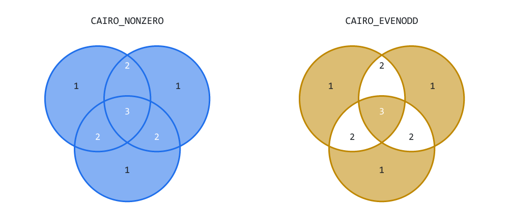
Figure 1. The same three contours under each rule, with the region numbers.
Figure 1 is not a drawing of the idea; it is the idea executed. Each pixel in both panels was shaded by accumulating the actual winding number at that point and asking the actual rule, so what you are looking at is what the rasterizer would produce.
Read the numbers. Three discs, all traced the same way round, give regions with winding 1 where one disc covers, 2 where two overlap, and 3 in the middle where all three do. The left panel keeps everything that is not 0, which is every region, so the three discs become one blob. The right panel keeps the odd regions — 1 and 3 — and drops the even ones, which punches the two-disc overlaps out and produces the interference pattern.
Same geometry. Same call. One enum value different.
Neither rule is better than the other, and it matters that you do not think of even-odd as "the one that does holes". They answer different questions, and by the end of this article we will have a case where non-zero is not merely preferable but required, and even-odd would destroy the drawing. Cairo, SVG and PostScript all expose both, for exactly this reason.
The change to the rasterizer
Here is the entire implementation, in three pieces.
First, the enum. It goes at the top of Raster.mqh, above the rasterizer class:
//+------------------------------------------------------------------+
//| ENUM_CAIRO_FILLRULE - what the winding number MEANS.             |
//+------------------------------------------------------------------+
enum ENUM_CAIRO_FILLRULE
  {
   CAIRO_NONZERO = 0,      // inside when winding != 0 - the default
   CAIRO_EVENODD = 1       // inside when the crossing count is odd
  };
The explicit values are not decoration. This enum may be saved in a theme file, passed through inputs, or serialized into widget state. If the compiler assigns the numeric values, inserting a new item in the middle can change the meaning of stored data.
Second, the parameter. Fill gains one argument, with a default:
   void              Fill(CCairoPath &path, const uint argb, uint &buffer[],
                          const int width, const int height,
                          const ENUM_CAIRO_FILLRULE rule = CAIRO_NONZERO);
The default is doing real work here. Every Fill() call written in Parts 3 and 4 — and every one in those articles' demos — keeps compiling and keeps behaving exactly as it did, because the behavior they were written against is the default. A new capability that forces you to revisit old call sites is a new capability with a tax attached.
That is the rasterizer's own signature, and it is the one the examples below are calling through a one-line wrapper the demo defines: Fill( path, color, rule = CAIRO_NONZERO ), which supplies the buffer and its dimensions and passes the rule straight on.
Third, the decision itself. Inside the sweep, one if becomes a ternary and an if:
That is the whole feature. Nothing else in Raster.mqh moves: the bounding box, the sub-scanlines, the crossing collection, the insertion sort, the coverage accumulator and the compositing pass are all untouched.
This is worth noting because it demonstrates the payoff of the library's structure: the change is minimal. From three statements in one function, the library gains holes, rings, borders, donut charts, gauges, progress tracks, and letter counters that come out as holes rather than as solid blobs. A glyph needs more than that — curves, an outline parser, the rule its font format assumes — but the part that belongs to the rasterizer is now here. This applies to all current shapes and to the ones later parts add.
That is only possible because there is exactly one function in the entire engine that decides what "inside" means. A library with a FillRect(), a FillTriangle() and a FillPolygon() would be adding this feature in three places today, and in five places a few parts from now.
         //--- sweep with the winding number, as before - but a span
         //--- is now ACCUMULATED rather than painted, and what the
         //--- winding number MEANS is now the caller's choice
         int winding = 0;

         for(int k = 0; k < n - 1; k++)
           {
            winding += m_cross_dir[k];

            //--- the fill rule, and the only line in this file
            //--- that Part 5 actually adds. (winding & 1) is a
            //--- valid parity test even though winding is a SIGNED
            //--- sum: every crossing adds +1 or -1, and both of
            //--- those flip the low bit, so the parity of the sum
            //--- equals the parity of the count.
            const bool inside = (rule == CAIRO_NONZERO)
                                ? (winding != 0)
                                : ((winding & 1) != 0);

            if(inside)
               AddSpan(m_cross_x[k], m_cross_x[k + 1],
                       weight, ix0, ix1);
           }
        }
There is a small cost worth naming honestly: the ternary is evaluated once per span, in the innermost loop. It is a comparison against a value that does not change for the duration of a fill, so it is about as predictable as a branch gets. How much that is worth depends on the compiler and the machine, and this article has not measured it. If it ever mattered, the fix is to hoist the test out of the loop and write two loop bodies — but do not do that until a profiler asks you to.
Why parity works on a signed sum
One line of that deserves its own section, because it looks wrong:
( winding & 1 ) != 0
We want the parity of the crossing count. What we have is winding, a signed sum — every crossing added either +1 or -1 to it. Testing the low bit of a signed sum as though it were a count looks like the kind of shortcut that works on the test case and fails in production.
It is exactly correct, and the reason is short. Each crossing changes the sum by +1 or -1, and both of those flip the low bit. Adding one flips it; subtracting one flips it too. So after k crossings, whatever mixture of directions occurred along the way, the low bit of the sum equals the parity of k.
Work through the cases:
crossings  +1, -1, +1   ->  sum = +1   odd sum,  3 crossings, odd count
crossings  -1, -1       ->  sum = -2   even sum, 2 crossings, even count
crossings  +1, +1, -1   ->  sum = +1   odd sum,  3 crossings, odd count
The one remaining thing to check is that MQL5's & behaves on negative numbers the way we need. It does: integers are two's complement, so -1 is all bits set and -1 & 1 is 1, while -2 ends in a zero bit and -2 & 1 is 0. There is no language corner case hiding here.
So a direction-independent rule falls out of a direction-dependent accumulator, for free, with no second counter to maintain and no extra work in the loop. This is the sort of thing that is obvious once you have seen it and impossible to invent under time pressure, which is why it is worth thirty seconds of your attention now.
The letter "A", at last
Part 3's demo drew a letter "A" and it came out solid. Both contours — the outer outline and the triangular counter in the middle — were traced the same way round, so the non-zero rule saw winding 1 in the body, winding 2 in the counter, and called both of them inside.
Part 3 offered a fix, and it worked: trace the counter backwards.
//--- the counter, deliberately traced the other way round
p.MoveTo( ox + 58, oy + 46 );
p.LineTo( ox + 68, oy + 80 );
p.LineTo( ox + 48, oy + 80 );
p.Close();
Look at what that demands, though. The artwork now has to encode a rendering decision in its vertex order. Whoever produces that geometry — a person typing coordinates, an exporter from a design tool, a font parser — has to know which contours are meant to be holes and has to reverse them. Get it wrong and the letter fills solid, with nothing in the code to point at.
Even-odd removes the requirement entirely:
CCairoPath a;
AddGlyphA( a, x, y );              // both contours wound naturally
Fill( a, fill_clr, CAIRO_EVENODD );
Both rules read the same crossing list, so both depend on the half-open [ytop, ybot) test from Part 3: it is what keeps a vertex shared by two edges from being counted twice, and a double count breaks parity exactly as readily as it breaks a winding sum.
The counter is a hole because it overlaps, not because it was traced a particular way. Panel B of the demo puts all three versions side by side: the solid failure, the hand-reversed fix, and the even-odd fix that needed no knowledge at all.
This is why font rasterizers and SVG renderers reach for even-odd, or for a non-zero convention enforced by the file format itself, as a matter of course. It is also a good general principle for a drawing API: when a rendering behavior can be selected at the call site, do not push it back into the data.
Borders: the wrong way and the right way
If you keep one section of this article, keep this one — not because the code is clever, but because the wrong way is a common approach in MQL5 panels, and the symptoms are things people usually blame on something else.
The common approach//--- fill a big rectangle in the border color CCairoPath outer; outer.AddRect( 20, 20, 170, 70 ); Fill( outer, border_color ); //--- then a smaller one in the BACKGROUND color on top CCairoPath inner; inner.AddRect( 26, 26, 158, 58 ); Fill( inner, background_color );
Two fills. The second paints over the middle of the first, and what is left looks like a frame. Over an opaque card this is entirely convincing, which is precisely why it survives in so much code. It has two faults.
Fault 1: it has to know the background color, and that color has to be opaque. Draw this over a region that is not a flat known color — a chart, a gradient, another widget, a panel with a soft drop shadow, or simply nothing at all — and the second fill puts an opaque patch where the interior should have been left alone. It cannot do otherwise. It has to paint something there, and the only thing it can paint is a guess.
That guess also becomes a maintenance liability. The day someone changes the panel background, every fake border in the codebase is silently wrong, and it is wrong in the least visible way possible: a slightly different shade of almost-the-same color, on a small region, that nobody notices until a screenshot lands in a bug report.
Fault 2: it blends two anti-aliased edges on top of each other. This one is new as of Part 4, and it is the sort of thing that only becomes visible once your renderer is good enough to be judged. The inner rectangle's smooth boundary is composited over the outer rectangle's interior, so the inner edge of the border is the result of two blends where the outer edge is the result of one. The border comes out very slightly asymmetric — crisper on the outside, muddier on the inside. At a hairline width, on a high-DPI screen, that is exactly enough to make a panel look subtly cheap without anyone being able to say why.
The right wayCCairoPath ring; ring.AddRect( 20, 20, 170, 70 ); // outer outline ring.AddRect( 26, 26, 158, 58 ); // inset copy Fill( ring, border_color, CAIRO_EVENODD );
One path. Two contours. One fill.
Follow a scanline across it. Entering the outer rectangle is crossing number one — odd, inside, so the left band is painted. Entering the inner rectangle is crossing number two — even, outside, so the interior is skipped. Leaving the inner rectangle is crossing three, odd, inside again: the right band is painted. Leaving the outer rectangle is crossing four, and we are out.
The interior is not painted in the background color. It is not painted at all. No pixel there is written to, so whatever was underneath survives untouched, including nothing at all. And each side of the band has exactly one anti-aliased edge, blended exactly once.
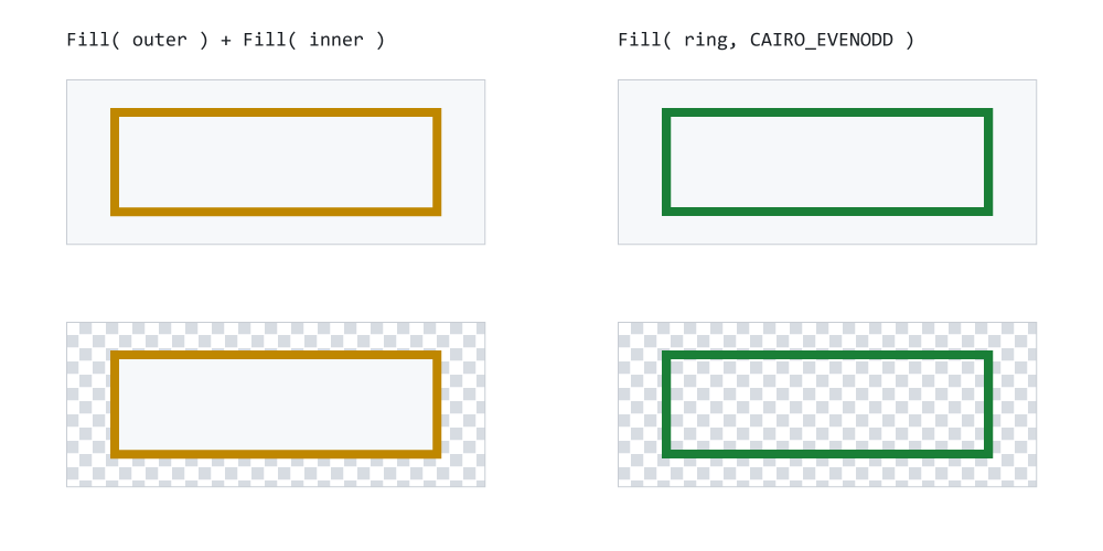
Figure 2. Two fills in the background color, against one even-odd ring.
Figure 2 makes the first fault visible by removing the assumption it depends on. The top row is over an opaque card, and the two are indistinguishable — which is the honest reason the fake version persists. The bottom row is over something the drawing code does not control, drawn here as a checkerboard. The fake border has painted a flat patch across it. The ring has not touched it.
The ring is not the only way to leave the interior alone — clipping, a mask or a separate layer would each do it too. It is the one that needs no machinery the engine does not already have.
The inset distance is the border width. A hairline and a sixteen-pixel band are the same two lines of code with one number changed, which panel D of the demo shows at five thicknesses. And there is no limit of two: four nested rectangles filled even-odd give concentric bands, because crossing count 1 is inside, 2 is outside, 3 is inside again, and so on for as long as you keep adding outlines.
Strokes built from fills
The engine has no stroker component, and this part does not add one. What it adds is a geometry helper: join styles, cap styles, a miter limit and dash patterns are all absent, and a caller who wants them builds them out of shapes. That is a design decision, not an omission, and this section is the argument for it.
A line with width is not a line. It is a shape — specifically a rectangle, rotated to lie along the segment. And a shape is something this library already draws, correctly, with anti-aliasing and compositing, through one function. So the "stroking" feature reduces to a geometry helper: given two endpoints and a thickness, produce four corners.
Here is the whole of AddThickLine, the one addition to Path.mqh this part makes:
//+------------------------------------------------------------------+
//| AddThickLine - one segment of a stroke, as a closed quad.        |
//+------------------------------------------------------------------+
void CCairoPath::AddThickLine(const double x0, const double y0,
                              const double x1, const double y1,
                              const double thickness)
  {
   const double dx  = x1 - x0;
   const double dy  = y1 - y0;
   const double len = MathSqrt(dx * dx + dy * dy);

//--- a zero-length segment has no direction, so it has no normal
//--- and no quad. Returning is correct; dividing is not.
   if(len < 1e-9)
      return;

//--- the quad is four vertices in one new contour
   ReservePoints(m_point_count + 4);

//--- unit normal, scaled to half the thickness
   const double nx = -dy / len * (thickness * 0.5);
   const double ny =  dx / len * (thickness * 0.5);

   MoveTo(x0 + nx, y0 + ny);
   LineTo(x0 - nx, y0 - ny);
   LineTo(x1 - nx, y1 - ny);
   LineTo(x1 + nx, y1 + ny);
   Close();
  }
Four things in there are worth reading slowly.
len is computed once and guarded. A zero-length segment has no direction, so it has no normal either, and every line after the guard would be dividing by zero. Returning quietly is the right behavior rather than an error, because zero-length segments arrive naturally: a polyline with a duplicated point, an animation frame where a value has not changed, a path built from live data that happened to repeat. The threshold 1e-9 is used instead of == 0.0 because the danger is not exact zero — MathSqrt(0) returns exactly zero — but a length so small that dividing by it produces a normal of absurd size from coordinates that differ only by rounding error.
(-dy, dx) is the normal. This is the only piece of mathematics in the function. On the usual mathematical axes, rotating a vector ninety degrees anticlockwise maps (dx, dy) to (-dy, dx); you can check it on a single case — the vector (1, 0), pointing right, becomes (0, 1), which is perpendicular to it. On screen, where y grows downward, that same result points down, so the rotation you see is clockwise; the arithmetic is unchanged either way. Nothing else about the direction survives, which is exactly what we want.
The division by len and the multiplication by thickness * 0.5 happen in one expression. Dividing by len makes the normal one unit long regardless of how long the segment is — without it, a long segment would produce a fat quad and a short one a thin quad from the same thickness argument. Then half the thickness is applied, because the quad extends both ways from the center line, so each side gets half.
The four corners come out in a fixed rotational order, and this is the part that looks cosmetic and is not. p0 + n, p0 - n, p1 - n, p1 + n traces the rectangle consistently for every segment, whichever way that segment points. The next section is entirely about what happens when that stops being true.
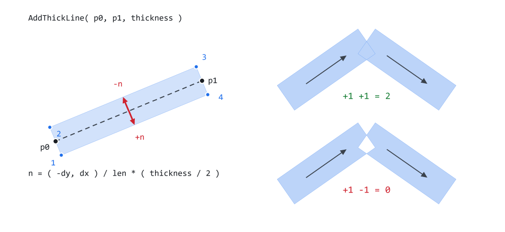
Figure 3. One segment as a quadrilateral, and what happens where two meet.
The left half is one call to AddThickLine(). The dashed line is the segment the caller asked for, n is the unit normal scaled to half the thickness, and the four numbered dots are the corners in the order they are emitted — always the same way round, whichever way the segment points.
The right half is a joint between two quads, shaded by running the non-zero rule for real. In the top bend both quads are wound the same way, the overlap has winding 2, and the bend is solid. In the bottom bend the second quad is wound backwards, the overlap sums to +1 - 1 = 0, and there is a hole at the corner. That hole is computed, not drawn in.
The part that matters: one path, one fillA polyline of thirty segments becomes thirty quads. Add a small polygon at each interior joint so the corners are not notched — the outer side of every bend is a wedge that neither quad covers — and all of it goes into a single path and is filled once, with the non-zero rule:
//+------------------------------------------------------------------+
//| E. STROKES BUILT FROM FILLS                                      |
//+------------------------------------------------------------------+
void PanelStroke(const double ox, const double oy)
  {
   const int    n = 34;
   const double thickness = 7.0;

   double vx[], vy[];

   if(ArrayResize(vx, n) < n)
      return;
   if(ArrayResize(vy, n) < n)
      return;

   for(int i = 0; i < n; i++)
     {
      vx[i] = ox + i * 12.0;
      vy[i] = oy + 55 + MathSin(i * 0.42) * 40
              + MathCos(i * 0.17) * 10;
     }

//--- ONE path for the whole polyline. The total is known, so the
//--- whole thing is one allocation instead of sixty-five.
   CCairoPath stroke;
   stroke.ReserveContours((n - 1) + (n - 2));
   stroke.ReservePoints((n - 1) * 4 + (n - 2) * 12);

   for(int i = 0; i < n - 1; i++)
      stroke.AddThickLine(vx[i], vy[i], vx[i + 1], vy[i + 1],
                          thickness);

//--- a small regular polygon at each interior joint, rounding it
   for(int i = 1; i < n - 1; i++)
      AddNGon(stroke, vx[i], vy[i], thickness * 0.5, 12);

   Fill(stroke, CairoWithOpacity(C_GREEN, 0.75), CAIRO_NONZERO);

   PrintFormat("E. stroke: %d segments + %d joints = %d contours, "
               "%d vertices, ONE fill, valid = %s",
               n - 1, n - 2, stroke.ContourCount(),
               stroke.PointCount(),
               stroke.IsValid() ? "true" : "false");
  }
The two Reserve calls are the Part 2 helpers earning their keep. Sixty-five contours and five hundred and sixteen vertices — 33 quads of four, 32 joint polygons of twelve — are known in advance, so the whole path is one allocation instead of dozens of small ones. They are not required — leave them out and the path still grows correctly — but when the count is on the line above, there is no reason to make the array find out the hard way.
Every quad is wound the same way, so at each joint the overlap has winding 2 — still non-zero, still inside — and the segments union seamlessly. There is no seam to hide, because the rasterizer never saw a seam: it saw one region.
Filling the quads separately would be slower, but slowness is the smaller problem. With a translucent color it would be visibly wrong. Each joint overlap would be blended twice, once for each quad, and every corner of the polyline would come out darker than the straight sections. One pass means one blend per pixel, so the stroke has uniform opacity along its whole length. The demo deliberately uses a 75%-opaque color so that you can check this rather than take my word for it.
And note which rule that requires. Under even-odd, a region covered by two quads and nothing else is crossed an even number of times and falls out, so the stroke would be notched at every bend. The joint polygons do not rescue it: where one of them overlaps two quads the count is odd again, so the corner would come back in patches rather than as a corner. The rule that makes borders possible would destroy strokes. This is what I meant earlier by "they answer different questions" — holding both is not indecision, it is the point.
The failure case: mixed winding
Back in Part 2 I claimed, without justification at the time, that every shape helper must wind its outline in a consistent direction, and said the reason would appear later. Here it is, and it is worth producing on purpose once so you can recognize it on sight.
The obvious way to reverse a segment is to swap its endpoints:
//--- this does NOT do what it looks like it does
bad.AddThickLine( x1, y1, x0, y0, thickness );
That does not reverse anything. Swapping the endpoints negates (dx, dy), which negates the normal, and the corners then come out as p1 - n, p1 + n, p0 + n, p0 - n — which is the same cycle as before, started at a different corner. Two flips cancel, and you get back the identical quad, wound the identical way. It is a good reminder that "reversed" is a property of the emitted order, not of the arguments.
What actually flips the winding is emitting the four corners in the opposite order, which is what the demo's local helper does:
//+------------------------------------------------------------------+
//| F. THE FAILURE CASE                                              |
//+------------------------------------------------------------------+
void AddThickLineReversed(CCairoPath &p, const double x0, const double y0,
                          const double x1, const double y1,
                          const double thickness)
  {
   const double dx  = x1 - x0;
   const double dy  = y1 - y0;
   const double len = MathSqrt(dx * dx + dy * dy);

   if(len < 1e-9)
      return;

   const double nx = -dy / len * (thickness * 0.5);
   const double ny =  dx / len * (thickness * 0.5);

//--- corners 4, 3, 2, 1 instead of 1, 2, 3, 4
   p.MoveTo(x1 + nx, y1 + ny);
   p.LineTo(x1 - nx, y1 - ny);
   p.LineTo(x0 - nx, y0 - ny);
   p.LineTo(x0 + nx, y0 + ny);
   p.Close();
  }
This helper is not library code, and it is not going into Path.mqh. It exists in the demo for one purpose: to build the bug deliberately. Panel F uses it on every second segment of the same polyline that panel E draws correctly.
Now the overlap at each joint has one quad contributing +1 and the other contributing -1. The winding number there is 0, the non-zero rule reads that as outside, and a hole opens at every single joint. The lower half of Figure 3 shows the mechanism on two segments; panel F shows it thirty-two times in a row, which is what it looks like when it happens to you by accident.
The generalization is the lesson: winding direction is part of your geometry's contract. Any helper that emits a contour has to document a direction and honor it, and any code that reverses a contour has to know that it is making a rendering decision, not a cosmetic one. That is the price of the non-zero rule, and it is a price worth paying for seamless unions — but it is not free, and pretending otherwise is how you end up staring at a stroke full of holes at two in the morning.
The demo
Demo05_FillRules.mq5 draws six panels into a single OBJ_BITMAP_LABEL. Every shape on the screen goes through the same Fill() call; the only thing that varies between panels is the geometry handed to it and, in three of them, the enum.
- A — three overlapping discs in one path, drawn twice. Identical geometry, identical call, one enum different. This is Figure 1 rendered by the engine itself rather than by the figure script.
- B — the letter "A" three ways: solid under non-zero, correct under non-zero with the counter hand-reversed, correct under even-odd with nothing reversed.
- C — the fake border and the true ring, each drawn twice: once over an opaque card, where they are indistinguishable, and once over a checkerboard, where they are not.
- D — rings at widths 1, 2, 4, 8 and 16 pixels, plus four nested rectangles showing that alternating bands work to any depth.
- E — a 34-point polyline stroked as 33 quads and 32 joint polygons, in one path, one fill, at 75% opacity. The log line reports the contour count, the vertex count and IsValid(), so a refused allocation would be visible rather than silent.
- F — the same polyline with alternating winding, failing.

Figure 4. Demo05_FillRules on a Black On White chart: six panels, one call.
One detail is worth noticing across the whole screen: AddNGon in the demo is not library code. It is a local helper that computes the vertices of a regular polygon, standing in for the circles we do not have yet. Every "disc" in panels A, D and E is a 72- or 96-sided polygon. The rasterizer cannot tell the difference, and neither can you at this size — which is the point Part 3 made about circles, and the point a later part will finally act on by computing those vertices for you.
The checkerboard in panel C is also demo code rather than library code. It stands in for whatever the caller had already drawn underneath, so that a fill which paints over things can be caught doing it. It is worth a glance at how it is built: several hundred squares are drawn, and there is exactly oneCCairoPath behind them. Clear() empties the path between squares while keeping the memory it has already been given, and Release() hands that memory back once the panel is finished. That is the Part 2 lifecycle pair doing what it was added for.
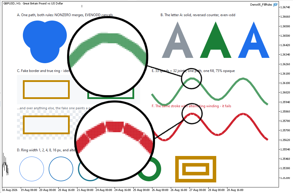
Figure 5. Panels E and F magnified: one seamless stroke, and one full of holes.
Figure 5 is the comparison to look at closely. On the left, the joints are invisible — not smoothed over, but genuinely absent, because the rasterizer filled one region rather than thirty-three overlapping ones. Check the opacity while you are there: it is constant along the stroke, including at the corners, which is the evidence that only one blend happened per pixel. On the right, the same geometry with alternate contours reversed, and the winding number falling to zero at every joint.
Project structure
Extract the archive under MQL5/, preserve the folder structure, and compile Demo05_FillRules.mq5. No paths need editing.
MQL5/
├── Include/
│   └── CairoG2D/
│       ├── Color.mqh          // the ARGB color type and blending
│       ├── Config.mqh         // CairoAaSamples - the quality dial
│       ├── Surface.mqh        // pixel buffer bound to one chart object
│       ├── Path.mqh           // the path and the edges, now + AddThickLine
│       ├── Raster.mqh         // the coverage fill, now + the fill rule
│       └── DemoTheme.mqh      // the demos' shared palette - NOT library code
└── Experts/
    └── CairoG2D/
        └── Article 05/
└── Demo05_FillRules.mq5 // six panels, one Fill() | # | File | Directory | Holds |
|---|---|---|---|
| 1 | Color.mqh | MQL5/Include/CairoG2D | the ARGB color type and CairoBlendOver |
| 2 | Config.mqh | MQL5/Include/CairoG2D | CairoAaSamples, and the version string |
| 3 | Surface.mqh | MQL5/Include/CairoG2D | CCairoSurface - pixel buffer to chart bitmap |
| 4 | Path.mqh | MQL5/Include/CairoG2D | the path, the edges, and now AddThickLine |
| 5 | Raster.mqh | MQL5/Include/CairoG2D | CCairoRasterizer - coverage, compositing, fill rule |
| 6 | DemoTheme.mqh | MQL5/Include/CairoG2D | palette, chart setup, captions - not library code |
| 7 | Demo05_FillRules.mq5 | MQL5/Experts/CairoG2D/Article 05 | six panels, including the winding failure |
| 8 | Cairo-Style Library - Part 05.zip | archive containing all the attached files and their paths relative to the terminal's root folder. |
Two files changed this part, and both only gained. Path.mqh gained AddThickLine at the end of its shape helpers; nothing above it moved. Raster.mqh gained ENUM_CAIRO_FILLRULE, one parameter on Fill() with a default, and the ternary in the sweep. Color.mqh, Config.mqh and Surface.mqh were not touched at all, and the attached include/ folder is exactly what the series has written so far — five files, and nothing from later parts.
What this does not solve, and what comes next
The change is deliberately tiny and practical: add an ENUM CAIRO FILLRULE and a rule parameter to Fill(), defaulting to the previous non-zero behavior so existing calls keep working. That single enum unlocks multiple, useful behaviors:
- CAIRO_EVENODD produces holes-by-construction: place an outer contour and an inset copy in one path and the interior is never painted — the underlying content survives untouched, and both edges are anti-aliased exactly once. This fixes letter counters and true borders without guessing background color.
- CAIRO_NONZERO allows building strokes from fills: emit quads for each segment (plus small joint polygons), put them in one path and fill once to avoid seams and double alpha blending. Non-zero preserves seamless unions but requires a consistent contour winding convention.
- The implementation is efficient and localized: one enum, one parameter, one ternary in the rasterizer's inner loop. Mixed winding remains the diagnostic to watch for — alternating contour direction creates holes at joints, so shape helpers must respect and document winding.
We did not add separate border or stroker subsystems; we leveraged the existing fill pipeline and geometry helpers to get more behavior for free. The next step is curves: adding CurveTo (cubic Beziers) and adaptive subdivision so rounded shapes can be emitted into the same vertex arrays without changing the downstream rasterizer or fill rules.
The project is supported on MQL5 Algo Forge. Each part of this series has its own release, frozen at exactly the code that part explains, so whichever article you are reading, its release is the one to download.
Part 5 is here: https://forge.mql5.io/SandroBegashvil/CairoG2D/releases/tag/part-05
Warning: All rights to these materials are reserved by MetaQuotes Ltd. Copying or reprinting of these materials in whole or in part is prohibited.
This article was written by a user of the site and reflects their personal views. MetaQuotes Ltd is not responsible for the accuracy of the information presented, nor for any consequences resulting from the use of the solutions, strategies or recommendations described.

 Money Management in MQL5 (Part 1): Kelly Position Sizing from the Strategy's Own Edge
 How to Implement Competition Among LLM Agents in MetaTrader 5
 Implementing and Comparing Five Historical Volatility Estimators in MQL5
 Neural Networks in Trading: A Unified View of Space and Time (Conclusion)

- Free trading apps
- Over 8,000 signals for copying
- Economic news for exploring financial markets
You agree to website policy and terms of use