

Neural Networks in Practice: An Example of Implementing an XOR Gate
 150
 0

Introduction
In my previous article, “Neural Networks in Practice: Practice Makes Perfect”, I explained how to speed up the calculation or adjustment of values within a simple neuron. And all of this is part of what I'm currently developing; I'll show you later how to implement it. I have absolutely no intention of showing you how to build a neural network for trading in the financial markets here. The goal is to explain as clearly and vividly as possible how a neural network is trained and, most importantly, how it works behind the scenes.
In that same article, I included a small table, which you can see below:
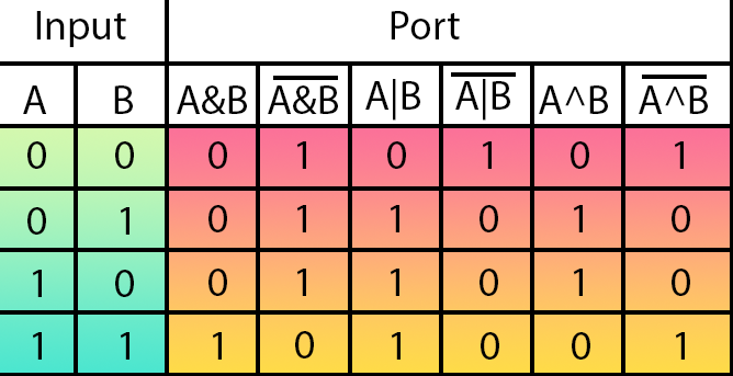
This small table, also known as a truth table, shows readers researching this topic or studying electronics how a circuit responds to the data fed into its inputs. In other words, by looking at this table, we can determine how an electronic device will work. Essentially, this shows the configurations of the basic logic gates that can be implemented. From left to right, we have the logic gates AND, NAND, OR, NOR, XOR, and XNOR.
Well, thanks to certain factors, our simple neuron is actually able to understand how the first four logic gates work. However, it can't figure out how the last two work. If you try to train an artificial neuron to understand how the XOR logic gate and its inversion—XNOR—work, it will not be able to generate the correct values to represent these gates. Why does this happen? The fact is that the logic underlying the XOR and XNOR logic gates is significantly more complex than that of the other logic gates.
Many people mistakenly believe that a neuron can learn to represent any case within a given domain. However, as you, my dear reader, can easily see, this is not the case. There are cases when a neural network—or, in this context, a neuron—is unable to understand or, more precisely, to learn something. Note that, although it may seem strange, this actually happens. That is exactly why I am highlighting this particular case. There are other cases as well where it can be more or less difficult to understand why a neural network or a neuron cannot learn to represent data properly. But this example, in which I use logic gates, is the easiest to explain. It's also the easiest example for everyone to follow and understand what's going on.
So, I think we all agree on what we've seen and described. So, we can continue our analysis. In my previous article, I set you a small challenge: try, my dear reader, to somehow get a single neuron to learn to represent the XOR logic gate or its inversion—the XNOR logic gate. To explain properly how we'll do this, let's move on to a new section.
A Little About Digital Electronics
What I'll try to explain here is covered in digital electronics courses. But this is also covered in mechatronics courses, where we learn to build machines and mechanisms that combine mechanical and electronic components. Mechatronics is one of the most advanced fields of study, as students often also have to study programming, operating systems, actuators, sensors, and much more. It therefore provides a very solid foundation for acquiring the concepts and knowledge needed to understand intelligent mechanisms or create human-machine interfaces. Without a doubt, this is one of those areas where you never stop being a student and always keep learning. Basically, the first thing I want to point out is that the solution we're looking for isn't always found in software. Often, it all comes down to knowledge from other fields.
To understand how we will control a neuron or make it represent an XOR gate or its inversion, we first need to understand how an XOR gate is constructed. Or, more precisely, how we can break it down to a more basic level. Contrary to popular belief, the XOR gate is not a simple function. In fact, it is a composite function consisting of several steps. However, I won't go into how the circuit is implemented using discrete components, such as transistors and other circuit elements. I won't go into detail about this part. In other words, I'll use other logic gates to explain how to tackle the problem of implementing an XOR gate and its inversion.
Now that you've reached this point, you might be thinking, "But this is crazy. Why would anyone do that?" Well, my dear reader, if you really want to understand how it all works, you'll need to explore a whole host of other topics. It's not enough to just wait for the program to give you an answer. You need to dig deeper. Here, however, we will only scratch the surface. Nevertheless, we'll look at the principles behind what we'll later be doing inside the neuron.
Well, there are several ways to represent the XOR gate and its inversion using other logic gates. The main question is this: how can we create an XOR gate using AND, NAND, OR, and NOR gates? Keep in mind that in this configuration, we can also use inverters to create an XOR gate. Thus, we can reduce everything to AND gates, OR gates, and inverters, since a NAND gate is an inverted AND gate, and a NOR gate is an inverted OR gate. This can be seen in the image in the previous section.
Since the goal is to create an XOR gate—or, more precisely, to correctly represent a logic gate of this type so that a neuron can form a representation of it—we need not take the simplification to the extreme and can use any other logic gate that the neuron is capable of representing. Here's what we're interested in: using a logic gate that our simple neuron can represent without errors. If you understand this, you'll be able to understand what we'll be doing here in this article.
Well, that's the easy part. The difficulty is that, as I mentioned earlier, an XOR gate can be constructed in several different ways using other logic gates. But to help you understand this, my dear reader, I won't just tell you which configuration I'll be using in this article. I'll show you which configuration will be used. You can see this in the following animation.
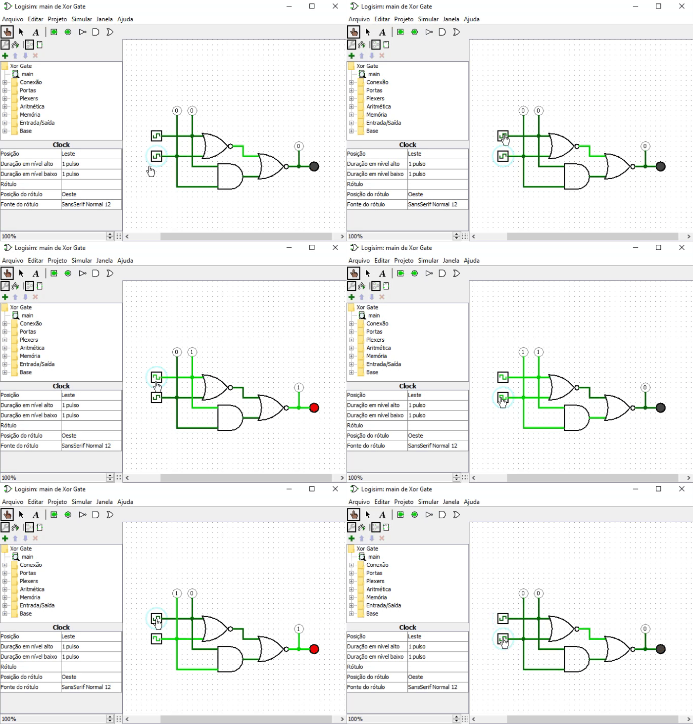
This animation was created in Logisim—an open-source program written in Java. Using this program, we can simulate electronic circuits in general to understand how they work. This is a pretty interesting—albeit old—program that lets us build and test different circuits without using expensive components or risking damaging them. The important point here, my dear reader, is that light green indicates the presence of voltage. In other words, we have logic level 1. Or, for programmers, the value "true."
The darker green lines represent logic level 0, that is, the value "false." At the circuit's inputs, we see the values from the truth table shown in the previous section. The output is shown as a circle that alternates between red and gray; this is exactly the output we want from the XOR gate in this case. Now, pay attention: both inputs are connected to two logic gates—the top one is a NOR gate, and the bottom one is an AND gate. The outputs of both gates are fed to another NOR gate, and the final result is precisely the output of this second NOR gate.
We could implement this system in several different ways. But here I decided to use this particular configuration for a very simple reason: it all comes down to understanding how the NOR gate and the AND gate work. Our simple neuron can correctly represent both logic gates. So, if we use the right implementation, we can use a trick to make the neuron represent a logic gate that it could not represent on its own. In other words, we will be able to implement an XOR logic gate using just a single neuron.
But wait a minute. Can we do things like that? Isn't that a bit like cheating? Well, there's no rule that would prevent us from doing that. Even if this is a bit of a trick and we're acting in a somewhat controversial way, I don't see any reason why we can't show how these things are done. So, let's now move on to the section on programming.
A dumb piece of silicon
Great—if you understood the previous topic, we've now reached the point where we'll prove that the machine will be whatever we choose to make it. It won't go beyond what we program it to do, even though many people think otherwise. A neural network is nothing more than a very well-structured computation. And since a computer is really just a slightly more powerful calculator, we can make this piece of silicon do exactly what we need it to do. And if it doesn't listen to us, we'll make it follow our orders until it gives in and realizes who's in charge here.
In the code below, we can see our initial neuron. This is the simplest version and does not optimize for the number of inputs. So you can add as many inputs as you need. But don't forget what we covered in the previous article.
//+------------------------------------------------------------------+
#property copyright "Daniel Jose"
//+------------------------------------------------------------------+
#define macroRandom (rand() / (double)SHORT_MAX)
#define macroSigmoid(a) (1.0 / (1 + MathExp(-a)))
//+------------------------------------------------------------------+
#define def_Fast
//+------------------------------------------------------------------+
double Train[][3] {
                    {0, 0, 0},
                    {0, 1, 0},
                    {1, 0, 0},
                    {1, 1, 1},
                  };
//+------------------------------------------------------------------+
const uint nTrain = Train.Size() / 3;
const double eps = 1e-3;
//+------------------------------------------------------------------+
double Cost(const double w0, const double w1, const double b)
{
    double err;

    err = 0;
    for (uint c = 0; c < nTrain; c++)
        err += MathPow((macroSigmoid((Train[c][0] * w0) + (Train[c][1] * w1) + b) - Train[c][2]), 2);

    return err / nTrain;
}
//+------------------------------------------------------------------+
void OnStart()
{
    double  w0, w1, err, ew0, ew1, eb, bias;
    ulong count, it0, it1;

    Print("The Neuron - Tutor...");
    MathSrand(512);
    w0 = (double)macroRandom;
    w1 = (double)macroRandom;
    bias = (double)macroRandom;

    it0 = GetTickCount();

    for (count = 0; (count < ULONG_MAX) && ((err = Cost(w0, w1, bias)) > eps); count++)
    {
        ew0 = (Cost(w0 + eps, w1, bias) - err) / eps;
        ew1 = (Cost(w0, w1 + eps, bias) - err) / eps;
        eb  = (Cost(w0, w1, bias + eps) - err) / eps;
        w0 -= (ew0 * eps);
        w1 -= (ew1 * eps);
        bias -= (eb * eps);
    }

    it1 = GetTickCount();
    Print("Time: ", (it1 - it0) / 1000.0, " seconds.");
    PrintFormat("%I64u > w0: %.4f %.4f || w1: %.4f %.4f || b: %.4f %.4f || %.4f", count, w0, ew0, w1, ew1, bias, eb, err);
    Print("w0 = ", w0, " || w1 = ", w1, " || Bias = ", bias);
    Print("Error Weight 0: ", ew0);
    Print("Error Weight 1: ", ew1);
    Print("Error Bias: ", eb);
    Print("Error: ", err);

    Print("************************************");
}
//+------------------------------------------------------------------+
So, this neuron cannot yet represent an XOR logic gate or its inversion. But what will happen if we train it to represent a NOR gate and an AND gate, and also show how to connect these gates to represent an XOR gate? Will this dumb piece of silicon then be able to understand how to represent an XOR logic gate? All right, let's see how to do this. Keep in mind that what I'm about to show you is just one of many possible and viable options. You, my dear reader, are free to try other options as well.
All right, first of all, we need to understand that we're going to build a small neural network inside a single simple neuron. To do this, we need to make the code behave as if we're doing one thing, even though we'll actually be doing something else. Since the neuron must learn to represent each of the logic gates, each gate will have two weights (w0 and w1) and a bias (b). This is because each logic gate has two inputs. In practice, each logic gate is equivalent to a single neuron. For this reason, we will have two weights and one bias for each logic gate implemented internally. Since we are using three logic gates, we will need four weights and two biases. But wait a minute. If each logic gate requires two weights and one bias, shouldn't the correct number be six weights and three biases? No, my dear reader. Since one of the logic gates—in this case, the NOR gate—will be duplicated, we do not need to account for it again. It may seem complicated, but in practice, it's much easier than it seems.
It is very important that you, my dear reader, understand this clearly. If you still don't understand this, reread the previous articles to understand why we need these weights and biases. But first, try to understand the explanation in the previous section so that you can grasp how we will use logic gates. If you still have any doubts about this, you won't understand what's actually happening inside the neuron.
All right, then I'll assume that you, my dear reader, understand what we need to do. So, the code shown above will be modified to look like the example below.
001. //+------------------------------------------------------------------+
002. #property copyright "Daniel Jose"
003. //+------------------------------------------------------------------+
004. #define macroRandom (rand() / (double)SHORT_MAX)
005. #define macroSigmoid(a) (1.0 / (1 + MathExp(-a)))
006. //+------------------------------------------------------------------+
007. #define def_Fast
008. //+------------------------------------------------------------------+
009. double  _NOR[][3] {
010.                     {0, 0, 1},
011.                     {0, 1, 0},
012.                     {1, 0, 0},
013.                     {1, 1, 0},
014.                   };
015. double  _AND[][3] {
016.                     {0, 0, 0},
017.                     {0, 1, 0},
018.                     {1, 0, 0},
019.                     {1, 1, 1},
020.                   };
021. struct st_XOR
022. {
023.     double Nor_w0, Nor_w1, Nor_bias, Nor_Err,
024.            And_w0, And_w1, And_bias, And_Err;
025. }_XOR;
026. //+------------------------------------------------------------------+
027. const uint nTrain = _NOR.Size() / 3;
028. const double eps = 1e-3;
029. //+------------------------------------------------------------------+
030. double Cost(const double w0, const double w1, const double b, const double &Train[][])
031. {
032.     double err;
033.
034.     err = 0;
035.     for (uint c = 0; c < nTrain; c++)
036.         err += MathPow((macroSigmoid((Train[c][0] * w0) + (Train[c][1] * w1) + b) - Train[c][2]), 2);
037.
038.     return err / nTrain;
039. }
040. //+------------------------------------------------------------------+
041. void OnStart()
042. {
043.     double ew0, ew1, eb;
044.     ulong count, it0, it1;
045.
046.     Print("The Neuron - Tutor...");
047.     MathSrand(512);
048.
049.     _XOR.Nor_w0 = (double)macroRandom;
050.     _XOR.Nor_w1 = (double)macroRandom;
051.     _XOR.Nor_bias = (double)macroRandom;
052.
053.     _XOR.And_w0 = (double)macroRandom;
054.     _XOR.And_w1 = (double)macroRandom;
055.     _XOR.And_bias = (double)macroRandom;
056.
057.     it0 = GetTickCount();
058.
059.     for (count = 0; count < ULONG_MAX; count++)
060.     {
061.         _XOR.Nor_Err = Cost(_XOR.Nor_w0, _XOR.Nor_w1, _XOR.Nor_bias, _NOR);
062.         _XOR.And_Err = Cost(_XOR.And_w0, _XOR.And_w1, _XOR.And_bias, _AND);
063.
064.         if ((_XOR.Nor_Err < eps) && (_XOR.And_Err < eps))
065.             break;
066.
067.         ew0 = ((Cost(_XOR.Nor_w0 + eps, _XOR.Nor_w1, _XOR.Nor_bias, _NOR) - _XOR.Nor_Err) / eps);
068.         ew1 = ((Cost(_XOR.Nor_w0, _XOR.Nor_w1 + eps, _XOR.Nor_bias, _NOR) - _XOR.Nor_Err) / eps);
069.         eb  = ((Cost(_XOR.Nor_w0, _XOR.Nor_w1, _XOR.Nor_bias + eps, _NOR) - _XOR.Nor_Err) / eps);
070.
071.         _XOR.Nor_w0 -= (ew0 * eps);
072.         _XOR.Nor_w1 -= (ew1 * eps);
073.         _XOR.Nor_bias -= (eb * eps);
074.
075.         ew0 = ((Cost(_XOR.And_w0 + eps, _XOR.And_w1, _XOR.And_bias, _AND) - _XOR.And_Err) / eps);
076.         ew1 = ((Cost(_XOR.And_w0, _XOR.And_w1 + eps, _XOR.And_bias, _AND) - _XOR.And_Err) / eps);
077.         eb  = ((Cost(_XOR.And_w0, _XOR.And_w1, _XOR.And_bias + eps, _AND) - _XOR.And_Err) / eps);
078.
079.         _XOR.And_w0 -= (ew0 * eps);
080.         _XOR.And_w1 -= (ew1 * eps);
081.         _XOR.And_bias -= (eb * eps);
082.     }
083.
084.     it1 = GetTickCount();
085.     Print("Time: ", (it1 - it0) / 1000.0, " seconds.");
086.     PrintFormat("Interactions: %I64u", count);
087.     Print("NOR port information:");
088.     Print("w0: ", _XOR.Nor_w0, " w1: ", _XOR.Nor_w1, " bias: ", _XOR.Nor_bias, " Error: ", _XOR.Nor_Err);
089.     Print("AND port information:");
090.     Print("w0: ", _XOR.And_w0, " w1: ", _XOR.And_w1, " bias: ", _XOR.And_bias, " Error: ", _XOR.And_Err);
091.
092.     Print("Testing the neuron...");
093.     for (uchar p0 = 0; p0 < 2; p0++)
094.         for (uchar p1 = 0; p1 < 2; p1++)
095.             PrintFormat("%d XOR %d IS %f", p0, p1, macroSigmoid((_XOR.Nor_w0 * macroSigmoid((p0 * _XOR.Nor_w0) + (p1 * _XOR.Nor_w1) + _XOR.Nor_bias)) +
096.                                                                 (_XOR.Nor_w1 * macroSigmoid((p0 * _XOR.And_w0) + (p1 * _XOR.And_w1) + _XOR.And_bias)) + _XOR.Nor_bias));
097.
098.     Print("************************************");
099. }
100. //+------------------------------------------------------------------+
And when you run this code in MetaTrader 5, you'll see something very similar to the following image.
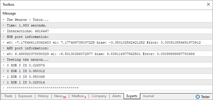
Note that the neuron has confirmed that it correctly represents the XOR logic gate. In other words, thanks to our help, it was able to understand how to represent the XOR logic gate. However, looking at the code above, you might be wondering exactly how this was done. This may seem extremely complicated and difficult to understand. However, if you take a close look at the code, you'll immediately notice that it's almost identical to the code we examined at the beginning of this topic. Then why does it have more code? And, besides, why—unlike in previous cases—aren't we including the truth table for the XOR logic gate in this code to train the neuron?
All right, those are perfectly valid questions. As for the first question, the answer is this: we need to instruct the neuron so that it learns to represent a NOR gate and an AND gate. That is apparently why we have more elements here. As for the second question, it would be correct to say that we do not need to train the neuron using the XOR gate's truth table. We'll take a clever approach and have it create a representation of a logic gate based on the values that the neuron itself generates for the NOR and AND logic gates. In this way, we will create in code the equivalent of the digital circuit discussed in the previous section.
Since we need to keep the data for each logic gate somewhat separate, in line 21 we create a structure to store the data needed to represent the XOR logic gate. But please note that we only have fields there for storing values of type double. There is no data or information that would support the claim that an XOR logic gate will actually be created.
The loss function in line 30 has been given an additional argument. Its purpose is to tell the loss function which data will be used during training. The rest of the loss function remains unchanged. In other words, the neuron remains in its most basic form. Thus, it can still do everything it could before if you want to use it outside this specific application, whose purpose is to represent an XOR logic gate.
On line 41, we begin the section specific to this application. At this stage, all the logic is contained within a single procedure. But even though this might seem complicated, it’s actually quite simple, and since I’ve broken down the code in a bit more detail, I think you, my dear reader, will be able to understand what’s going on.
On lines 49–51, we initialize the weights and bias for the NOR logic gate. The same thing happens on lines 53 through 55, except that here we initialize the values for the AND logic gate. Please note that we initialize the system with pseudorandom values. We have done this before, as you can see in the code at the beginning of this section. The difference is that previously we initialized values for only one logic gate, but now we do so for two.
Okay, now on line 59 we enter a for loop whose purpose is to get the neuron to find a way to represent logic gates using data from the training arrays. Again, this might seem complicated. But we've been doing exactly this kind of thing for some time now. The difference from previous cases is that we are now training the neuron to represent not one, but two different logic gates. So, the first thing we need to do is determine the initial error for each of the logic gates. This is done on line 61, where we obtain the error for the NOR logic gate, and on line 62, where we obtain the error for the AND logic gate. Since we need to check two values to end the loop as soon as possible, on line 64 we check whether the error is below the expected level. If that is the case, line 65 will cause the loop to end. Otherwise, we will move on to the next step in the loop.
The next step is to use finite differences to estimate the gradient and move toward a lower-cost point. First, we'll do this for the NOR gate. You can see this in lines 67 through 73. In these lines of code, we're performing exactly the same calculations as before, so this shouldn't pose any difficulty for those who have been following our articles. Now that we have performed the calculations for the NOR gate, we will do the same for the AND gate. This is done in lines 75 through 81.
In this way, we get the neuron to represent what it is capable of understanding, namely the AND and NOR logic gates. Note that, contrary to what one might have assumed at first, we do not need to train a third logic gate. In other words, first figure out what needs to be done, and then do what you originally planned.In lines 84 through 90, we print a set of data to verify the results we obtained. Remember that the basic idea behind a neural network is to create an equation that represents the data. The fact that it gives rise to something that many consider intelligent is merely a detail. Finally, in lines 92 through 96, we display the representation that the neuron generates for the XOR logic gate.
Understanding the Results
"My friend, I've figured out most of the code, since I've been studying your programs quite closely. I noticed that we actually trained the NOR gate and the AND gate so that the neuron would learn to represent these gates. But as for that last part, where we output the result and get exactly what we need to represent the XOR logic gate—my friend, I didn't understand at all what was going on there. Could you explain this part in a little more detail?"
Of course. Of course, I can explain what's happening in this final part of the code. I know that at first glance this might seem rather unusual and a bit complicated. But perhaps that's because you were expecting to see a particular piece of code. And when you look at the code used to represent the XOR logic gate, you see something completely different from what you expected. To understand this properly, I want you to follow the sequence of images below and pay attention to what happens in the code snippets that follow. The idea is to break down the final code into even smaller parts so that it will be much easier for us to explain what's going on here, my dear reader.
Let's start with the NOR logic gate shown in BLUE in the image below, which is the first to receive the input data.
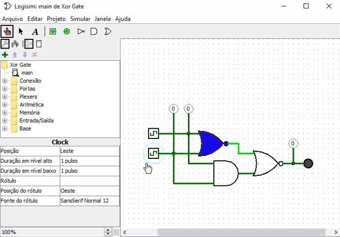
The code snippet corresponding to the same logic gate shown in the previous image is also highlighted below.
PrintFormat("%d XOR %d IS %f", p0, p1, macroSigmoid((_XOR.Nor_w0 * macroSigmoid((p0 * _XOR.Nor_w0) + (p1 * _XOR.Nor_w1) + _XOR.Nor_bias)) +
                                                    (_XOR.Nor_w1 * macroSigmoid((p0 * _XOR.And_w0) + (p1 * _XOR.And_w1) + _XOR.And_bias)) + _XOR.Nor_bias));
Great—please note that this is the first of the logic gates shown. Now let's take a look at the next logic gate—the AND gate, which is shown in green in the following image.
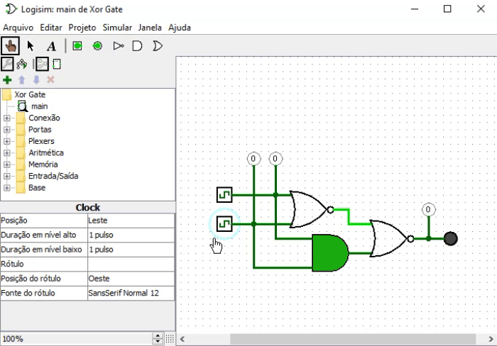
The same AND logic gate highlighted in green in the previous image is also highlighted in green in the code snippet below.
PrintFormat("%d XOR %d IS %f", p0, p1, macroSigmoid((_XOR.Nor_w0 * macroSigmoid((p0 * _XOR.Nor_w0) + (p1 * _XOR.Nor_w1) + _XOR.Nor_bias)) +
                                                    (_XOR.Nor_w1 * macroSigmoid((p0 * _XOR.And_w0) + (p1 * _XOR.And_w1) + _XOR.And_bias)) + _XOR.Nor_bias));
Please note that this is the same code snippet. And now—the grand finale: the final NOR gate, highlighted in red in the following image.
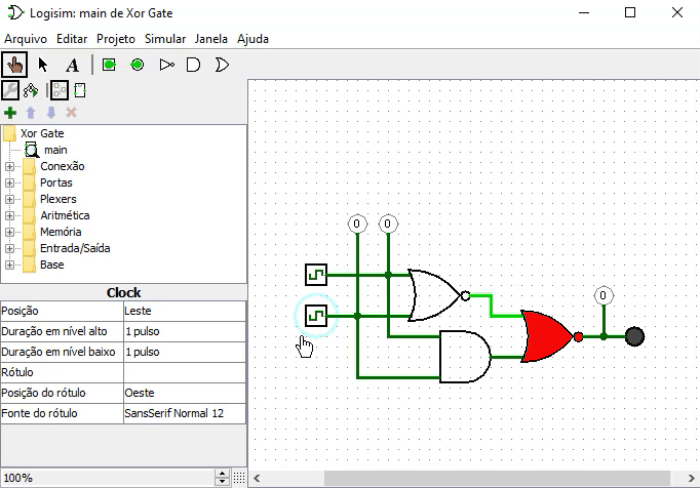
Since all the code in this snippet pertains to this last logic gate, I'll just point out where its parameters are located. In other words, its inputs are precisely the outputs of the other logic gates. However, it requires the weights and bias of the original NOR logic gate. And that is precisely what is highlighted in the following code snippet.
PrintFormat("%d XOR %d IS %f", p0, p1, macroSigmoid((_XOR.Nor_w0 * macroSigmoid((p0 * _XOR.Nor_w0) + (p1 * _XOR.Nor_w1) + _XOR.Nor_bias)) +
                                                    (_XOR.Nor_w1 * macroSigmoid((p0 * _XOR.And_w0) + (p1 * _XOR.And_w1) + _XOR.And_bias)) + _XOR.Nor_bias));
I think that concludes the explanation. Nevertheless, I would like to propose a challenge to you, my dear reader, so that you can see for yourself whether you have understood the points made in this article.
A Challenge for You, the Reader
Let's do it this way: in the attached file, you'll find both the code we discussed in this article to represent the XOR logic gate and the code containing the solution to this challenge. However, I want you to be honest and try to tackle this challenge before looking at the answer or a possible solution. Okay, is that a deal?
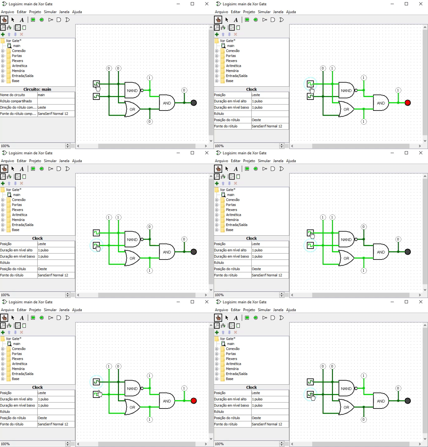
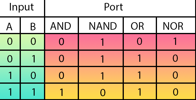
All right, if the answer is “yes,” let’s move on to the challenge. It will be something simple and related to what we've covered in this article. I want you to try designing a training process that enables a single neuron to represent an XOR gate, but in a different way from what we've considered so far. I want you to examine the circuit in the following animation and design a solution using the logic gates in that circuit. Since many of you probably aren't familiar with electronics, I'll show you the truth table for each of the logic gates. In any case, try watching the animation first, since it clearly shows what's happening.
The truth table you can use is shown in the following image.
One thing to note: to tackle this challenge, try doing something similar to what we discussed in this article. However, you'll need to set up a few things a little differently. Now, if you've really got the hang of this and want a slightly tougher challenge, try creating a neuron that can do what's shown in the following animation.
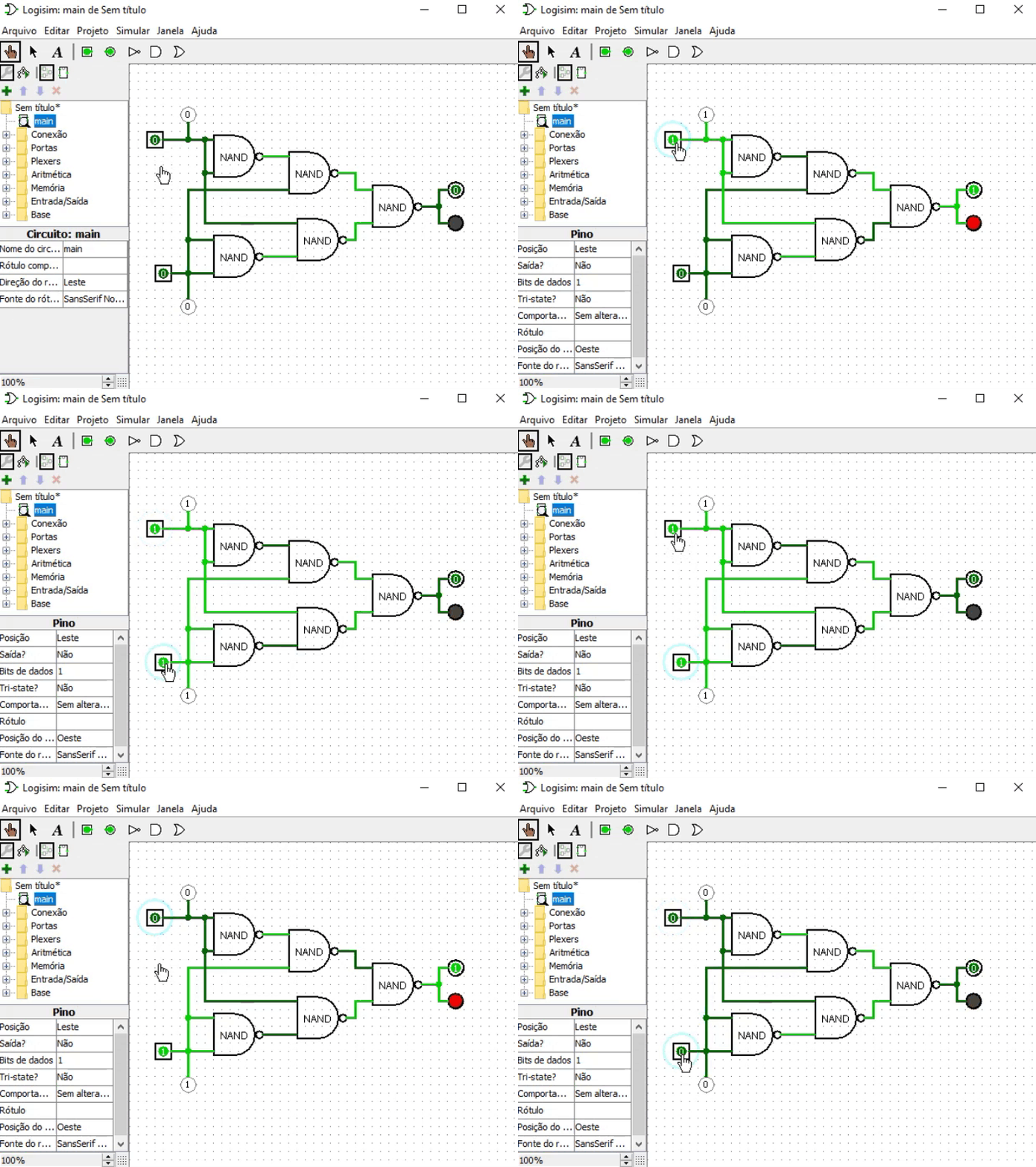
In this case, we use only NAND gates, and yet the final result is a representation of an XOR gate. Now that could be a good challenge if you want to try adjusting the neuron's output. But it's not hard to do. All you need is a little patience to get the right result.
Concluding Thoughts
In this article, I have tried to show you, my dear reader, that things are not always what they seem. We often tend to think that everything is arranged in a certain way, even though we may end up believing something that isn't necessarily true. Neural networks are undoubtedly one of the most interesting topics, whether viewed from the perspectives of mathematics, electronics, or software. Contrary to what many people think or claim, neural networks are neither a problem nor a definitive solution. This is just one area of research where we should continue to delve deeper and explore what goes on behind the scenes.
When it comes to neural networks, you shouldn't blindly trust anyone. In fact, over the years, I've noticed that the more research into neural networks advances, the more lies and rumors emerge. In fact, neural networks have been studied for many years, if not decades. Nevertheless, I've noticed that many people simply ignore this fact and believe that the topic has already peaked. And yet, there is still much to be done. As you may have already noticed, there is no single, universal way to represent models of all types. As simple as it may seem, there is still no way to adequately represent everything in the world.
In the field of neural networks, there is still ample room for research, improvement, and further study. No matter how advanced neural networks that can generate images or even text may seem, they still lack something essential: critical thinking and common sense. In any case, we still have many other aspects of this topic to discuss. Well then, see you in the next article.| MQ5 File | Description |
|---|---|
| Appendix | Basic Demonstration |
| Challenge 01 | Basic Demonstration |
| Challenge 02 | Basic Demonstration |
Translated from Portuguese by MetaQuotes Ltd.
Original article: https://www.mql5.com/pt/articles/13782
Warning: All rights to these materials are reserved by MetaQuotes Ltd. Copying or reprinting of these materials in whole or in part is prohibited.
This article was written by a user of the site and reflects their personal views. MetaQuotes Ltd is not responsible for the accuracy of the information presented, nor for any consequences resulting from the use of the solutions, strategies or recommendations described.

 From Basic to Intermediate: Operator Overloading (VI)
 How to Train an MLP Using Markov Chain Features in MQL5
 Color Harmony Algorithm (CHA)
 Creating a Cairo-Inspired Graphics Library for MetaTrader 5 (Part 7): Arcs, Circles and Rounded Rectangles

- Free trading apps
- Over 8,000 signals for copying
- Economic news for exploring financial markets
You agree to website policy and terms of use