

Creating a Cairo-Inspired Graphics Library for MetaTrader 5 (Part 3): Edges and the First Filled Shape
 547
547
 0
0

Contents
- Introduction
- What scan conversion actually is
- The edge: a segment rewritten for the question
- The winding number
- The rasterizer
- The demo
- Project structure
- Conclusion and the Road Ahead
Introduction
Part 2 built the geometry layer. We can describe a rectangle, a star, a font glyph or a two-thousand-vertex blob. Every one of them comes out as the same kind of data: points with double coordinates, grouped into contours, stored flat. What we could not do was draw any of it. The demo plotted vertices and wireframes, because that was all the library could honestly manage.
Today the shapes become solid. They do so through one function that has never heard of rectangles or stars. Give it a path and a color, and it fills the path. That is the entire public surface of the rasterizer:
g_ras.Fill(path, color, buffer, width, height);
Every shape in this part's demo goes through that call and no other. There are six shapes in the first row alone, plus a glyph, a fan of thin triangles and a 2000-edge flower. Compare it with Part 1, where a triangle and a circle needed two separate routines that shared not one line.
Getting there takes two pieces. The first is the edge: a segment rewritten into the form that answers the only question a scanline renderer ever asks. The second is the scanline sweep itself. It walks the buffer one row at a time, finds where that row crosses the outline, and decides which stretches are inside using the winding number.
Both ideas are older than most of the software you use. The scanline fill dates to the 1960s and has not needed replacing. The later parts—anti-aliasing, fill rules, clipping, and the active edge table—refine the four steps described today; they do not replace them.
Three things this version does badly, all of them on purpose, and all of them stated again where they happen in the code:
- it takes one sample per row, so every edge that is not exactly horizontal or vertical comes out as a staircase;
- it overwrites pixels rather than blending, so a translucent color does not composite with what is underneath;
- it implements only the non-zero fill rule, so a letter O fills solid unless its inner contour is wound opposite to the outer one.
None of those are shortcuts to apologize for. Each is a separate idea. Mixing all of them into one article is exactly what makes a rasterizer feel like magic instead of a mechanism.
Here is the state of the library when we are done today:
Color.mqh      Part 1    the ARGB color type, uint 0xAARRGGBB
Surface.mqh    Part 1    a pixel buffer bound to one chart object
Path.mqh       Part 2    points, contours, MoveTo / LineTo / Close
                         and one closed flag per contour
               Part 3    + SCairoEdge, CCairoEdgeList, BuildEdges   <- today
Raster.mqh     Part 3    the scanline fill                          <- today
What scan conversion actually is
A path is a mathematical outline with infinite precision. A buffer is a grid of little squares, and each square can hold exactly one color. Scan conversion is the act of deciding what color each square should be, given an outline that pays no attention to the grid.
Put like that, the problem sounds impossible to organize. The outline can be any shape at all, and the grid has hundreds of thousands of cells. The idea that makes it manageable is to stop thinking about the shape as a whole, and to think about one horizontal line at a time.
Take a single horizontal line through the middle of one row of pixels. That line either misses the shape completely, or it enters and leaves it. It may do so several times, if the shape is concave or has more than one contour. Between entering and leaving, every pixel on that line is inside. So the two-dimensional question "which pixels are inside this shape?" becomes a one-dimensional question asked once per row: where does this line enter and leave?
That question has an exact answer, and it is cheap. A line crosses a straight segment at most once, and finding where takes one subtraction, one multiply and one add. Do it for every segment, sort the answers, and the row is solved.
The whole algorithm, per row:
1. take a horizontal line through the middle of the row
2. find every edge that line crosses, and at what x
3. sort those crossings from left to right
4. walk them, tracking a winding number, and paint the stretches inside
Four steps. The rest of this article is those four steps written out, plus the one piece of preparation that makes step 2 fast.
The edge: a segment rewritten for the question
Step 2 runs once per edge, per row. A shape 400 pixels tall with 200 segments asks it 80,000 times for a single fill. So the form the segment is stored in matters more than anything else in this article.
A path stores a segment the way it was written: from the vertex the pen was at, to the vertex the pen moved to. That is the right form for building geometry and the wrong form for querying it. So before filling, every segment is converted once into an edge. It is the same line, rewritten so that "where do you cross the line at y?" is answered immediately.
//+-------------------------------------------------------------------+
//| SCairoEdge - one segment, pre-processed for scanline queries.     |
//+-------------------------------------------------------------------+
struct SCairoEdge
  {
   double            ytop;       // smaller y
   double            ybot;       // larger y
   double            xtop;       // x at ytop
   double            dxdy;       // slope: how far x moves per unit of y
   int               dir;        // +1 the original segment ran downward, -1 upward

   //--- x where this edge crosses the horizontal line at y.
   //--- One multiply and one add - which is the whole reason the
   //--- struct is laid out like this.
   double            XAt(const double y) const { return xtop + (y - ytop) * dxdy; }
  };
XAt() is the reason the struct is laid out this way. One subtraction, one multiply, one add, and no branches. The division that computes dxdy happens once, when the edge is built, instead of once per row.
Two decisions in those six lines deserve unpacking. Both look arbitrary and neither is.
Every edge is stored top-down. Whichever way the original segment ran, the edge records the smaller y as ytop. That means the test "does the line at y cross this edge?" is always y >= ytop && y < ybot, with no need to work out which end is which first. In the inner loop of a renderer, removing a branch that runs 80,000 times per shape is worth a little care at build time.
The direction is not thrown away. Flipping the segment loses something real: whether the outline was traveling downward or upward at this point. That single bit is kept in dir, and it is not bookkeeping. It is this edge's contribution to the winding number. Without it we could still fill simple shapes with the even-odd rule. With it we get the non-zero rule: self-overlap that merges, and holes chosen by direction.
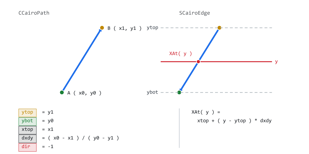
Figure 1. One segment, as the path wrote it and as the edge list stores it.
Figure 1 shows a segment that runs upward on screen. The pen was low and moved high, so y0 > y1. On the left is what Path.mqh holds. On the right is the edge. The geometry is identical, the same two endpoints and the same line, but the arrow has been turned round so that ytop really is the top. dir has been set to -1 to record that the flip happened. The red line is a scanline, and the dot on it is what XAt() returns.
Building an edge//+-------------------------------------------------------------------+ //| Turn one segment into one edge. | //+-------------------------------------------------------------------+ void CCairoEdgeList::Add(const double x0, const double y0, const double x1, const double y1) { //--- a horizontal segment is crossed by no scanline, so it can //--- never contribute a crossing. Dropping it here keeps the //--- rasterizer's inner loop free of a special case. if(y0 == y1) return; const int i = m_count; //--- grow in blocks of 64, not one slot at a time. A refused //--- resize drops the edge instead of writing past the end. if(ArraySize(m_edges) < m_count + 1) if(ArrayResize(m_edges, m_count + 1, 64) < m_count + 1) return; m_count++; if(y0 < y1) { //--- the segment runs downward in screen space m_edges[i].dir = 1; m_edges[i].ytop = y0; m_edges[i].ybot = y1; m_edges[i].xtop = x0; m_edges[i].dxdy = (x1 - x0) / (y1 - y0); } else { //--- the segment runs upward: store it flipped, and REMEMBER //--- the flip in dir - that memory is the winding number m_edges[i].dir = -1; m_edges[i].ytop = y1; m_edges[i].ybot = y0; m_edges[i].xtop = x1; m_edges[i].dxdy = (x0 - x1) / (y0 - y1); } }
The early return on a horizontal segment is worth more than it costs. A horizontal segment is parallel to every scanline, so no scanline crosses it and it can never contribute a crossing. Dropping it here means the inner loop never has to consider it. More importantly, it means the division that computes dxdy can never divide by zero. The guard and the safety are the same line of code.
The two branches are mirror images. Note that dxdy comes out identical in both. (x1 - x0) / (y1 - y0) and (x0 - x1) / (y0 - y1) are the same number, because both signs flip. Only the starting point differs, because xtop must be the x at whichever end is now on top.
The reserve of 64 is the same technique Part 2 used on the point array, for the same reason and with the same payoff. A path with 2000 segments allocates about thirty times instead of two thousand.
The return value of ArrayResize() is checked for the same reason Part 2 checks it. If the memory is refused and the code carries on, the next line writes past the end of the array, and MQL5 stops the program with an array out of range error. Here the edge is dropped instead. The shape may then fill incomplete, which is a smaller problem than a stopped program.
The edge list//+-------------------------------------------------------------------+ //| CCairoEdgeList - a growable array of edges, reused between fills. | //+-------------------------------------------------------------------+ class CCairoEdgeList { public: SCairoEdge m_edges[]; int m_count; CCairoEdgeList(); void Clear(); void Reserve(const int capacity); void Add(const double x0, const double y0, const double x1, const double y1); }; //+-------------------------------------------------------------------+ //| Constructor | //+-------------------------------------------------------------------+ CCairoEdgeList::CCairoEdgeList() { m_count = 0; ArrayResize(m_edges, 0); } //+-------------------------------------------------------------------+ //| Reset the count. The allocation is kept on purpose. | //+-------------------------------------------------------------------+ void CCairoEdgeList::Clear() { m_count = 0; } //+-------------------------------------------------------------------+ //| Ask for room for capacity edges before the first one arrives. | //+-------------------------------------------------------------------+ void CCairoEdgeList::Reserve(const int capacity) { if(capacity > ArraySize(m_edges)) ArrayResize(m_edges, capacity); }
The members are public and the class is deliberately simple. It is a buffer the rasterizer walks, not an abstraction with opinions. As Part 1 established, MQL5 has no pointer-to-array type, so an accessor that hands out m_edges could not be written even if we wanted one.
Clear() resets the count and does not touch the array. That is the whole trick that makes repeated fills cheap. After a few shapes the allocation has reached its high-water mark and never grows again. A Clear() that also freed the memory would make every fill pay for the last one's allocation.
This is the same size and capacity split the path itself uses. m_count is the number of valid edges. ArraySize(m_edges) is the capacity, and it is always equal to or larger than the count. Nothing may walk the list with ArraySize().
Reserve() is here for the reason ReservePoints() is in the path. The caller often knows the final count before the first edge arrives, and one allocation of the right size costs less than several that grow into it. A refused resize does no harm here, because Add() checks the size on every append anyway, so the list simply grows the slow way.
Where the closing segment is drawn
Close() in Part 2 marks a contour as closed. It stores no vertex, and it never did: the closing segment is not in the point array of any path. This is the function that produces it.
//+-------------------------------------------------------------------+
//| BuildEdges - turn every contour into edges.                       |
//+-------------------------------------------------------------------+
void CCairoPath::BuildEdges(CCairoEdgeList &out)
  {
   out.Clear();

//--- a path that was refused memory is not geometry we can trust,
//--- and half a shape on screen is worse than no shape at all
   if(!IsValid())
      return;

//--- each contour emits exactly as many edges as it has vertices,
//--- so the total is known before the loop starts
   out.Reserve(m_point_count);

   for(int c = 0; c < m_contour_count; c++)
     {
      const int start = m_starts[c];
      const int count = ContourLength(c);

      //--- one vertex encloses no area, so it produces no edges
      if(count < 2)
         continue;

      for(int i = 0; i < count; i++)
        {
         const int a = start + i;
         const int b = start + ((i + 1) % count);       // wrap = auto-close

         out.Add(m_points[a].x, m_points[a].y,
                 m_points[b].x, m_points[b].y);
        }
     }
  }
The whole of "closing" is ( i + 1 ) % count. On the last vertex of a contour that expression wraps back to the first, and produces the segment nobody stored. That is also why the loop runs i < count rather than i < count - 1. A four-vertex rectangle produces four edges, not three.
Now read the loop again and note what it does not test. It never looks at the closed flag. Every contour is closed here, including the ones the author left open. That is correct rather than careless. A fill needs a boundary with no gap in it, because an outline with a gap has no inside. This library therefore fills an open contour as the shape it would be if it were closed. It could reject open contours instead, but implicit closing is the convention in Cairo, SVG and HTML Canvas.
So the path and the fill give two different answers about the same contour, and both are right. The flag says what the author wrote, and stroking will read it in a later part to decide between a joint and two end caps. This loop says what a fill has to do. The demo shows both at once. The nameless blob in row A is built with AddPolyline(), the path reports it as open, and it still fills solid.
There is one more point about the flag: timing. After BuildEdges() returns, downstream code cannot distinguish open from closed contours, because edges do not carry that information. That is exactly why the flag has to be recorded in Part 2, while the author is writing the path. It cannot be recovered afterwards by checking whether the first and last vertex happen to match.
Two short guards open the function. IsValid() refuses to build edges from a path that lost an allocation while it was being built, because a partial outline fills as a wrong shape rather than as no shape. Reserve() then asks for the whole edge array in one call. Every contour emits at most as many edges as it has vertices, so m_point_count is a safe upper bound before the loop starts.
Notice also that this function is the last place in the pipeline that knows about contours. It walks the flat point array and the start indices from Part 2, and it emits a single undifferentiated list of edges. From here on, the rasterizer cannot tell how many contours the path had, in which order they were written, or which vertex belonged to which. It does not need to. Everything it must know about the structure of the shape is already encoded in the dir field of the individual edges.
The winding number
Step 4 determines which intervals of the scanline lie inside the shape.
Once a row's crossings are sorted, we have a list of x positions where the outline was met, left to right. The obvious rule is to alternate: outside, inside, outside, inside. Fill every other stretch. For a simple shape that works perfectly, and it is what the even-odd rule does.
It breaks the moment a shape overlaps itself.
Picture two squares in one path, offset so they overlap in the middle. A scanline through the overlap meets four edges. Alternating says: stretch one is inside, stretch two, the overlap, is outside, and stretch three is inside. The result is a hole punched through the middle of two shapes that were both meant to be solid. Anyone who has drawn a thick line as a chain of overlapping quadrilaterals has seen exactly this: a transparent notch at every joint.
The winding number fixes it by counting instead of alternating. Start outside, with a counter at zero. At each crossing, add the edge's dir: +1 for an edge that ran downward, -1 for one that ran upward. The stretch after a crossing is inside when the counter is not zero.
Walk that through the two overlapping squares. Both are traced the same way round. Entering the first square adds +1, so we are inside. Entering the second while still inside the first adds another +1, giving 2. That is not zero, so we are still inside, and the overlap fills. Leaving the first subtracts 1, back to 1, still inside. Leaving the second returns to 0, outside. The two squares merge into one solid region with no seam, which is what anyone drawing them would expect.
Now trace the second square the other way round. Entering it now adds -1 instead of +1, so in the overlap the counter reads +1 -1 = 0. That means outside, and a hole appears exactly where the two shapes cross.
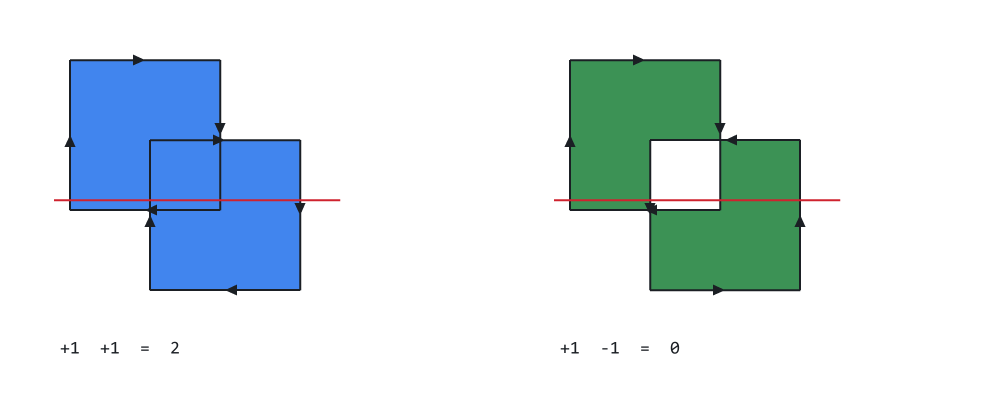
Figure 2. Same two squares: wound alike they merge, wound opposite they cancel.
Figure 2 is the whole idea in one picture. Both halves were produced by running the winding rule itself, not by drawing what it ought to look like. The arrows on each outline show the direction it was traced. On the left both squares run clockwise and the overlap is solid. On the right the second square runs the other way and the overlap has been cut clean out. The geometry is identical, the fill call is identical, and only the order the vertices were written in differs.
This is what Part 2 meant when it said that a consistent vertex order in the shape helpers is a convention worth keeping. Under the non-zero rule what matters is the relative direction of two contours: a hole must be wound against the outline that contains it. The library never re-winds anything, so that relationship stays under the caller's control. It is also the mechanism used deliberately for creating rings, frames, and letters with counters.
The rasterizer
Raster.mqh contains the CCairoRasterizer class, whose main operation is Fill().
//+-------------------------------------------------------------------+
//| CCairoRasterizer                                                  |
//+-------------------------------------------------------------------+
class CCairoRasterizer
  {
private:
   CCairoEdgeList    m_edges;        // edges of the path being filled
   double            m_cross_x[];    // where this scanline crosses each edge
   int               m_cross_dir[];  // and in which direction

   bool              EnsureCapacity(const int edge_count);
   void              SortCrossings(const int n);

public:
                     CCairoRasterizer();

   void              Fill(CCairoPath &path, const uint argb, uint &buffer[],
                          const int width, const int height);
  };
The class stores reusable scratch arrays for scanline crossings. Their capacity grows as needed and is retained between fills, avoiding repeated allocations when the same rasterizer instance is reused.
//+-------------------------------------------------------------------+
//| Grow the scratch arrays if needed. They are never shrunk.         |
//+-------------------------------------------------------------------+
bool CCairoRasterizer::EnsureCapacity(const int edge_count)
  {
   if(ArraySize(m_cross_x) >= edge_count)
      return true;

   if(ArrayResize(m_cross_x,   edge_count) < edge_count)
      return false;
   if(ArrayResize(m_cross_dir, edge_count) < edge_count)
      return false;

   return true;
  }
Sizing to the edge count is both sufficient and simple. A single horizontal line cannot cross more edges than the path has.
Both resize operations are checked. Continuing after an allocation failure would stop the program with an array out of range error. Note that the early test looks at m_cross_x only, so it assumes both arrays always grow together.
Sorting the crossings//+-------------------------------------------------------------------+ //| Sort this scanline's crossings from left to right. | //+-------------------------------------------------------------------+ void CCairoRasterizer::SortCrossings(const int n) { for(int i = 1; i < n; i++) { const double key_x = m_cross_x[i]; const int key_dir = m_cross_dir[i]; int j = i - 1; while(j >= 0 && m_cross_x[j] > key_x) { m_cross_x[j + 1] = m_cross_x[j]; m_cross_dir[j + 1] = m_cross_dir[j]; j--; } m_cross_x[j + 1] = key_x; m_cross_dir[j + 1] = key_dir; } }
Insertion sort is suitable here because the number of crossings on a single scanline is usually small.
n is not the number of edges in the path. It is the number of edges crossing one horizontal line. That is two for a triangle, two for a circle, four for a ring or a chevron, and rarely more than a dozen even for a detailed icon. At that size insertion sort is typically faster than a general-purpose sort, because it has no setup cost, no recursion, and no memory traffic beyond the array itself. A quicksort on eight elements spends more time deciding what to do than doing it.
It has a second advantage that this version does not use yet. Consecutive scanlines produce almost the same ordering. The crossings drift sideways a little from row to row, but they rarely swap places. Here the crossings are collected again in edge-list order on every row, so that order is not reused. The active edge table in Part 9 keeps it, and insertion sort runs close to linear on nearly sorted input.
One detail is not optional: x and dir must move together. They are two halves of one record, split across two arrays for speed, and swapping one without the other would silently corrupt the winding calculation. The bug it produces is a shape that fills correctly on most rows and inverts on a few.
The fill, step by step
The signature first:
//+-------------------------------------------------------------------+
//| Fill `path` with the color `argb` into an ARGB buffer.            |
//+-------------------------------------------------------------------+
void CCairoRasterizer::Fill(CCairoPath &path, const uint argb,
                            uint &buffer[],
                            const int width, const int height)
  {
The buffer is width * height uint in 0xAARRGGBB, row-major. That is exactly what CCairoSurface owns and exactly what ResourceCreate expects, so no conversion happens anywhere in the pipeline. Fill() does not check the buffer size, so the caller must pass a buffer of at least width * height elements. The path is taken by reference because MQL5 would otherwise copy it.
Step 0 turns contours into edges:
//--- STEP 0 - turn contours into edges.

   path.BuildEdges(m_edges);

   const int edge_count = m_edges.m_count;

   if(edge_count == 0)
      return;

   if(!EnsureCapacity(edge_count))
      return;                        // no scratch room - draw nothing
Everything after this line has forgotten what shape it is drawing. That sentence is the design of the whole library in one clause.
Step 1 works out which rows the shape can possibly touch:
//--- STEP 1 - which rows can this shape possibly touch?

   double ymin =  1e18;
   double ymax = -1e18;

   for(int i = 0; i < edge_count; i++)
     {
      if(m_edges.m_edges[i].ytop < ymin)
         ymin = m_edges.m_edges[i].ytop;
      if(m_edges.m_edges[i].ybot > ymax)
         ymax = m_edges.m_edges[i].ybot;
     }

   int iy0 = (int)MathFloor(ymin);
   int iy1 = (int)MathCeil(ymax);

   if(iy0 < 0)
      iy0 = 0;
   if(iy1 > height)
      iy1 = height;

//--- entirely above or below the buffer
   if(iy1 <= iy0)
      return;
This is the cheapest optimization in the engine and one of the most important. Without it, filling a 16-pixel icon on an 800-pixel-tall panel would walk all 800 rows and test every edge on each of them. That is 784 rows of work to discover that nothing happens there. With it, the cost of a shape depends on the rows the shape covers times its edge count, not on the buffer.
That property is what makes a dashboard of many small widgets viable at all. A panel with sixty small elements is sixty small costs, not sixty full-buffer sweeps. It is also the first appearance of an idea Part 9 develops properly: never touch a pixel you can prove you do not need.
The clamping to [0, height) is the only bounds checking the row loop needs. Doing it once here means the inner loop can write to the buffer without testing y at all.
Step 2 walks the rows:
//--- STEP 2 - walk the rows.

   for(int iy = iy0; iy < iy1; iy++)
     {

      //--- Sample at the CENTER of the row, never at its edge.
      const double yc = iy + 0.5;
Sample at the center of the row, never at its edge. A shape whose boundary lands exactly on a pixel boundary is ambiguous if you sample there. It flickers between covered and not as it moves by a hair, which in an animated panel shows up as a row that blinks. Half a pixel down, away from integer coordinates where most geometry sits, such cases become rare, and the half-open test below settles the ones that remain. This is the same + 0.5 that Part 1 used in its hand-written triangle, and for the same reason.
Step 3 finds the crossings:
      //--- STEP 3 - find every edge this line crosses.


      int n = 0;

      for(int i = 0; i < edge_count; i++)
        {
         if(yc >= m_edges.m_edges[i].ytop &&
            yc <  m_edges.m_edges[i].ybot)
           {
            m_cross_x[n]   = m_edges.m_edges[i].XAt(yc);
            m_cross_dir[n] = m_edges.m_edges[i].dir;
            n++;
           }
        }

      //--- fewer than two crossings can never enclose an interior
      if(n < 2)
         continue;

      SortCrossings(n);
The test is half-open: [ytop, ybot). That asymmetry is not a detail to gloss over. It is the single most common source of bugs in a hand-written rasterizer.
Two edges of a contour meet at a shared vertex. If both ends of the test were inclusive, a scanline passing exactly through that vertex would find both edges and count the crossing twice. The winding number would then be wrong for the whole rest of the row, off by one and in the wrong direction. The result is a one-pixel pinhole, or a thin bright streak running off the side of the shape. Where the outline passes through a vertex, half-open counts it exactly once. The edge that ends there fails the < ybot test, and the edge that begins there passes the >= ytop one. At a local top both edges are counted, and at a local bottom neither is; either way their contributions cancel and the winding stays correct.
This bug is rare by construction, which makes it dangerous. It occurs only when a vertex lands exactly on a row center, so casual testing may miss it. It can then surface later on a specific shape at a specific position.
Step 4 sweeps left to right:
      //--- STEP 4 - sweep left to right, tracking the WINDING NUMBER.

      int winding = 0;

      for(int k = 0; k < n - 1; k++)
        {
         winding += m_cross_dir[k];

         if(winding == 0)
            continue;                    // this stretch is outside

         //--- paint from crossing k to crossing k+1
         //--- Rounding to whole pixels is what makes this version
         //--- jagged: the span really begins at, say, x = 10.3, and
         //--- we are pretending it begins at 10. Future parts stops
         //--- pretending.
         int xa = (int)MathRound(m_cross_x[k]);
         int xb = (int)MathRound(m_cross_x[k + 1]);

         if(xa < 0)
            xa = 0;
         if(xb > width)
            xb = width;

         const int row_base = iy * width;

         for(int x = xa; x < xb; x++)
            buffer[row_base + x] = argb;
        }
     }
  }
The loop runs to n - 1 because it works on the stretch between crossing k and crossing k + 1. There is no stretch after the last one.
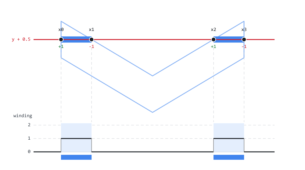
Figure 3. One row through a chevron: four crossings, and the winding beneath.
Figure 3 is that loop, drawn. The shape is a chevron, chosen because it is concave. A single row goes inside, then outside, then inside again. The four crossings are marked with their dir values, and the step plot below tracks the winding number as the sweep moves right. The two shaded stretches are where it is not zero, and they are the two spans that get painted.
Two lines in that step deserve a comment.
MathRound on the span ends is what makes this version jagged. The span really begins at, say, x = 10.3, and we are pretending it begins at 10. Every fractional position that Part 2 worked so hard to preserve is discarded right here, at the last possible moment. Later stops pretending, and that one change is what removes every staircase in the demo.
The assignment buffer[row_base + x] = argb overwrites. Whatever was in that pixel is gone, however transparent the incoming color claims to be. Blending needs the same machinery as anti-aliasing, because both are arithmetic on a fractional weight, so both arrive together in next parts.
The demo
Demo03_FirstFill.mq5 draws everything through one helper, and the helper is the point:
//+-------------------------------------------------------------------+
//| One call for every shape in this demo.                            |
//+-------------------------------------------------------------------+
void Fill(CCairoPath &p, const uint argb)
  {
   if(!p.IsValid())
     {
      Print("Cairo5: path incomplete - out of memory while building it");
      return;
     }

   g_ras.Fill(p, argb, g_surface.m_px,
              g_surface.Width(), g_surface.Height());
  }
Note what is absent from the argument list: any hint of what kind of shape this is. Every shape below calls this and nothing else.
The one test is the health flag from Part 2. A path records a refused allocation instead of writing past the end of its array, so a caller can ask once, at the end, whether everything it asked for arrived. Here that costs one comparison per shape, and it means a shape either appears correctly or does not appear at all. Half a shape is the worse of the two outcomes, because it looks like a drawing bug rather than a memory problem.
Row A: six shapes, one function. A rectangle from AddRect(), a triangle from AddTriangle(), a ten-vertex star from AddPolygon(), a seven-vertex blob from AddPolyline(), and a 300-sided polygon:
//--- and a 300-sided polygon, which is what a circle really is.
//--- Part 7 will compute these vertices for us; today we do it
//--- by hand, and the rasterizer cannot tell the difference.
   const int n = 300;

   double cx[], cy[];

   ArrayResize(cx, n);
   ArrayResize(cy, n);

   for(int i = 0; i < n; i++)
     {
      const double a = 2.0 * M_PI * i / n;

      cx[i] = 830 + 52 * MathCos(a);
      cy[i] = oy + 55 + 52 * MathSin(a);
     }

   CCairoPath circle;
   circle.ReservePoints(n);            // the count is known: one allocation
   circle.AddPolygon(cx, cy, n);
   Fill(circle, DEMO_RED);
That last shape is a circle. Note how little the library knows about it: there is no circle primitive, no arc code, and no special case in Raster.mqh. There is a loop that computes 300 points on a circle and hands them over as a polygon. The rasterizer sees 300 edges, exactly as it would for a 300-sided gear, and fills them in the same way. Part 7 will supply the vertices for us and choose how many to use. It will not touch the renderer.
ReservePoints() is the small habit worth picking up here. The loop above knows that 300 vertices are coming, so the path can be given room for all of them before the first one is stored, instead of growing five times on the way. Part 7 will do the same when it computes arc vertices.
The blob is in the demo for the same reason as the circle, but from the other direction. It is a shape with no name at all, seven arbitrary vertices, and it fills as correctly as the rectangle does. It also makes the point of the earlier section visible:
//--- an arbitrary blob nobody has a name for, to make the point
//--- that the rasterizer does not care. This one is built with
//--- AddPolyline, so the path records it as an OPEN contour -
//--- and it still fills solid, because BuildEdges joins the last
//--- vertex back to the first for every contour. Fill has no
//--- other option; the flag is there for the stroking in a later
//--- part, which does have a choice to make.
   double bx[7], by[7];

   bx[0] = 590;
   by[0] = oy + 20;
   bx[1] = 690;
   by[1] = oy;
   bx[2] = 730;
   by[2] = oy + 60;
   bx[3] = 690;
   by[3] = oy + 105;
   bx[4] = 640;
   by[4] = oy + 70;
   bx[5] = 615;
   by[5] = oy + 100;
   bx[6] = 575;
   by[6] = oy + 65;

   CCairoPath blob;
   blob.AddPolyline(bx, by, 7);

   PrintFormat("the blob: %d contour, closed = %s - and it fills anyway",
               blob.ContourCount(),
               blob.IsContourClosed(0) ? "true" : "false");

   Fill(blob, DEMO_INK_SOFT);
AddPolyline() does not call Close(), so the path reports the contour as open, and the log says so. On screen the blob is a solid shape all the same, because BuildEdges() joined its last vertex back to its first. The path keeps the author's answer, and the fill closes it implicitly.
Row B: the winding experiment. Two overlapping squares, twice, with the second contour reversed the second time. Both contours and all eight vertices are known in advance, so they are asked for in one call each:
//--- LEFT: both squares clockwise on screen
   CCairoPath same;

   same.ReserveContours(2);
   same.ReservePoints(8);
Then the second path, with its second contour traced the other way round:
//--- note the vertex order: bottom-left, bottom-right, top-right,
//--- top-left - the opposite rotation to the contour above
   opposite.MoveTo(420, oy + 165);
   opposite.LineTo(530, oy + 165);
   opposite.LineTo(530, oy +  55);
   opposite.LineTo(420, oy +  55);
   opposite.Close();
This is Figure 2 running for real, in the terminal, from the library rather than from a Python script. Run it and change one of those four lines to see the hole open and close.
Row C: the glyph. The letter A from Part 2, filled. Both contours are wound the same way, so the counter does not become a hole. The letter fills as a solid blob, which is not what a letter should look like. The demo then draws it again with the counter reversed, which does produce a proper A.
That first version is not a bug in the demo. It is the honest state of the engine. With only the non-zero rule, a font glyph fills solid unless the caller winds its counter the opposite way. The even-odd rule will allow holes to appear without requiring the caller to think about vertex order.
Row D: the staircase. A fan of seven thin triangles at shallow angles:
//+-------------------------------------------------------------------+
//| D. THE STAIRCASE, MADE OBVIOUS                                    |
//+-------------------------------------------------------------------+
void RowStaircase(const double ox, const double oy)
  {
//--- ONE path for all seven triangles. Clear() empties it without
//--- giving the memory back, so the first triangle pays for the
//--- allocation and the other six reuse it. This is the loop a
//--- dashboard runs on every tick, in miniature.
   CCairoPath t;

   for(int i = 0; i < 7; i++)
     {
      const double a = -M_PI * 0.5 + M_PI * 0.5 * i / 6.0;

      t.Clear();
      t.AddTriangle(ox, oy + 120,
                    ox + 150 * MathCos(a),
                    oy + 120 + 150 * MathSin(a),
                    ox + 150 * MathCos(a + 0.09),
                    oy + 120 + 150 * MathSin(a + 0.09));

      Fill(t, CairoLerp(DEMO_BLUE, DEMO_AMBER, i / 6.0));
     }

//--- the shape is finished with, so hand the memory back
   t.Release();
  }
One path is built seven times, not seven paths built once each. Clear() empties it and keeps the memory, so the first triangle pays for the allocation and the other six reuse it. Release() at the end gives the memory back, because this path is finished with. That pair is a small thing in a demo of seven triangles and a large one in a dashboard that rebuilds its geometry on every tick.
The angles are shallow on purpose. As Part 1 established, a 45-degree edge steps one pixel per pixel and reads as a fairly convincing line. A shallow edge runs level for three or four pixels and then drops a whole one, and there is no mistaking it. This row is the exact figure to compare against next part.
The flower. Finally, one path with 2000 vertices, timed:
//--- one shape with a great many edges, to show that complexity
//--- costs time inside our buffer and nothing at all on the chart
   const int n = 2000;

   double xs[], ys[];

   ArrayResize(xs, n);
   ArrayResize(ys, n);

   for(int i = 0; i < n; i++)
     {
      const double a = 2.0 * M_PI * i / n;
      const double r = 70.0 + 22.0 * MathSin(a * 11.0);

      xs[i] = 700 + r * MathCos(a);
      ys[i] = 510 + r * MathSin(a);
     }

   CCairoPath flower;
   flower.AddPolygon(xs, ys, n);

//--- these vertices came out of arithmetic, so check them once
//--- before they reach the rasterizer. A NaN found here has an
//--- address; the same NaN found by the fill is a blank panel.
   if(!flower.IsFinite())
      Print("Cairo5: the flower has a coordinate that is not a number");
   else
     {
      const ulong t0 = GetMicrosecondCount();
      Fill(flower, DEMO_BLUE);
      const ulong t1 = GetMicrosecondCount();

      PrintFormat("a %d-edge path filled in %d us", n, (int)(t1 - t0));
     }
IsFinite() is used here to validate coordinates produced by arithmetic before the path reaches the rasterizer. The check is optional and is performed where the geometry is generated rather than during every fill. Fill() itself does not test for NaN or infinity, so this check is the caller's responsibility.
The 2000-edge example is included to measure how the rasterizer handles a relatively large path. The result is still rendered through the same single chart object used by the other examples.
The timing uses GetMicrosecondCount for the reason Part 1 gave. On Windows, GetTickCount advances in steps of about 15.6 ms, so it would report this as either 0 or 15, and neither number would mean anything.
What to look at 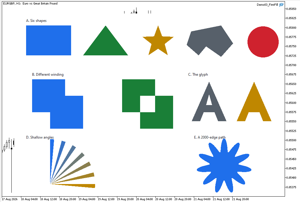
Figure 4. Demo03_FirstFill on a Black On White chart: every shape is solid.
Figure 4 is the context shot. Every filled region in it came from the same Fill() call. Work along row A and note that the 300-sided polygon on the right is indistinguishable from a circle at this size. Note also that the nameless blob beside it is as clean as the rectangle, although it was written as an open polyline.
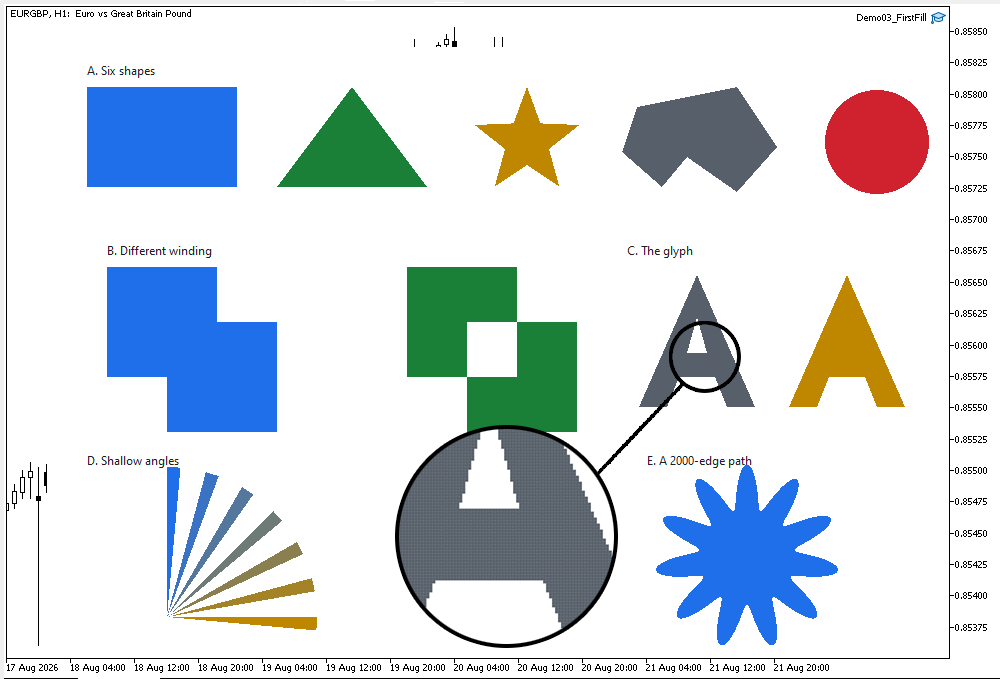
Figure 5. The staircase row enlarged: every edge pixel is fully on or off.
Figure 5 is the one to remember. Magnified with no smoothing, every boundary pixel is either full color or full background. There is no intermediate value anywhere, because the rasterizer never computed one. Compare the shallow triangles at the bottom of the fan with the steeper ones at the top. The shallower the angle, the longer the treads and the worse it looks.
The log reports the state of the blob and the two timings:
=== Part 3: one Fill() for every shape ===
the blob: 1 contour, closed = false - and it fills anyway
a 2000-edge path filled in 1673 us
whole 920x640 frame in 4412 us, 1 chart object
Those numbers will differ on your machine, and the absolute values matter less than the shape of them. The 2000-edge flower takes a noticeable fraction of the whole frame, because step 3 currently tests every edge against every row. A 2000-edge shape spanning 180 rows performs 360,000 range tests to find perhaps four crossings per row. That is the naive part of this naive rasterizer, and it is what the active edge table in Part 9 removes.
Project structure
The attached archive contains the complete source for this part. Extract it under MQL5/, preserve the folder structure, and compile Demo03_FirstFill.mq5. No paths need editing.
MQL5/
├── Include/
│   └── CairoG2D/
│       ├── Color.mqh          // the ARGB color type
│       ├── Surface.mqh        // pixel buffer bound to one chart object
│       ├── Path.mqh           // the path, and now the edges
│       ├── Raster.mqh         // the scanline fill
│       └── DemoTheme.mqh      // the demos' shared palette - NOT library code
└── Experts/
    └── CairoG2D/
        └── Article 03/
            └── Demo03_FirstFill.mq5  // every shape through one Fill()
The layout is the one Part 2 introduced and does not change again. Library headers live under MQL5/Include/CairoG2D/, and the demos sit under MQL5/Experts/CairoG2D/.
| # | File | Directory | What it holds |
|---|---|---|---|
| 1 | Color.mqh | MQL5/Include/CairoG2D | the ARGB color type, constructors, interpolation |
| 2 | Surface.mqh | MQL5/Include/CairoG2D | CCairoSurface - pixel buffer to chart bitmap |
| 3 | Path.mqh | MQL5/Include/CairoG2D | the path, plus SCairoEdge, CCairoEdgeList and BuildEdges() |
| 4 | Raster.mqh | MQL5/Include/CairoG2D | CCairoRasterizer - the scanline fill |
| 5 | DemoTheme.mqh | MQL5/Include/CairoG2D | palette, chart setup, captions - not library code |
| 6 | Demo03_FirstFill.mq5 | MQL5/Experts/CairoG2D/Article 03/ | six shapes, the winding experiment, the staircase |
| 7 | Cairo-Style Library - Part 03.zip | archive containing all the attached files and their paths relative to the terminal's root folder. |
Path.mqh is the only earlier file this part touches, and the path model in it is unchanged. SCairoEdge, CCairoEdgeList and BuildEdges() were appended to the file. The storage, the verbs and the accessors from Part 2 work exactly as they did, and everything Part 2's demo does still works without a single edit.
Conclusion and the Road Ahead
The library can now fill any outline that can be described with straight segments, and it does so with one function that contains no per-shape code of any kind. A rectangle, a star, a glyph, a 2000-edge flower and a shape nobody has named all take the same route. Contours become edges, edges are queried once per row, the crossings are sorted, and the winding number decides which stretches are inside.
The pieces that made it possible are worth naming again, because each will continue to serve as a foundation for the rest of the series:
- the edge, a segment rewritten so that XAt(y) is one subtraction, one multiply and one add;
- top-down storage with a remembered direction, which is what turns four arbitrary crossings into a well-defined inside and outside;
- the winding number, which merges overlapping contours instead of punching holes in them, while also supporting intentional holes when needed;
- and the y-range clamp, so that the cost depends on the rows a shape covers, not on how large the buffer is.
It is also worth naming what did not change. The path from Part 2 is the same path. Edges are built from it on demand and thrown away after the fill, so the geometry layer never learns anything about pixels, and the closed flag it stores survives untouched for the features that depend on it.
What we have is also visibly unfinished in two ways, and both are visible in Figure 5. The edges are staircases, and the fill overwrites instead of blending. The third limitation, the non-zero rule only, is the subject of Part 5.
We will address both issues together, because they turn out to be connected. The yes/no test at the row center is replaced by a measurement. Instead of asking whether a pixel is inside, we ask what fraction of it is inside, and that fraction becomes the pixel's coverage. The span ends stop being rounded, the partly covered pixels at each end of a span get a proportional share of the color, and the staircase dissolves into a smooth edge.
Coverage then needs somewhere to go, and that is alpha compositing. A pixel with coverage 0.3 must be mixed 30% into what is already in the buffer rather than overwriting it. We will write CairoBlendOver, work through the arithmetic with real numbers, and deal with the straight versus pre-multiplied question that Part 1 flagged and deferred.
The result is the single largest visual jump in the series. The same demo shapes, the same paths, the same four steps, and edges that look like edges.
The project is supported on MQL5 Algo Forge. Each part of this series has its own release, frozen at exactly the code that part explains, so whichever article you are reading, its release is the one to download.
Part 3 is here: https://forge.mql5.io/SandroBegashvil/CairoG2D/releases/tag/part-03
Warning: All rights to these materials are reserved by MetaQuotes Ltd. Copying or reprinting of these materials in whole or in part is prohibited.
This article was written by a user of the site and reflects their personal views. MetaQuotes Ltd is not responsible for the accuracy of the information presented, nor for any consequences resulting from the use of the solutions, strategies or recommendations described.

 Building a Neural Loss-Pattern Auditor in MQL5
 Random Matrix Theory: Denoising the Correlation Matrix for Multi-Symbol EAs
 Artificial Searching Swarm Algorithm (ASSA)
 Drawdown Duration Analysis Indicator in MQL5

- Free trading apps
- Over 8,000 signals for copying
- Economic news for exploring financial markets
You agree to website policy and terms of use