

Creating a Cairo-Inspired Graphics Library for MetaTrader 5 (Part 4): Anti-Aliasing, Coverage and Compositing
 49
49
 0
0

Contents
- Introduction
- Coverage, exactly
- Config.mqh: one number, at runtime
- CairoBlendOver: putting one color on top of another
- The rasterizer, second version
- The demo
- Project structure
- Conclusion, and what comes next
Introduction
You draw shapes into a buffer and display them on a chart or UI, and everything looks fine — until diagonal edges and translucency reveal the limits. Any edge that is not exactly horizontal or vertical becomes a visible “staircase,” slender elements can vanish, and semi‑transparent fills can overwrite what was underneath instead of blending with it. These are not unrelated bugs: they come from the same root cause. The rasterizer in Part 3 answered the yes/no question “is the pixel center inside the shape?” (0 or 1). What we need is a quantitative answer: “what FRACTION of this pixel is inside?” — a coverage value between 0 and 1.
In this part we introduce that coverage number and use it in the compositing step so anti‑aliasing and alpha blending are handled by the same arithmetic. Coverage is computed exactly in X (interval subtraction) and approximated in Y by N horizontal sub‑scanlines (CairoAaSamples). The implementation changes are small and local: the rasterizer gains a coverage accumulator and AddSpan to credit fractional pixels, Color.mqh gains CairoBlendOver to multiply coverage into source alpha, and Config.mqh exposes the runtime quality dial. Measurable goals: straight edges should become smooth without a separate smoothing pass, translucent overlaps should produce correct compositing, and the CairoAaSamples setting should give a clear, measurable quality/speed tradeoff.
Part 3 built a rasterizer that fills any outline through one function. It works, it has no per-shape code anywhere, and it produced the first solid shapes in this series. It also has two faults, both visible in its final figure:
- every edge that is not exactly horizontal or vertical comes out as a staircase;
- a translucent color overwrites what is underneath instead of blending with it.
Those look like two separate problems, and most renderers treat them that way, but they share the same cause. Both come down to a single missing number — how much — and once that number exists, both are solved by the same three lines of arithmetic.
Here is the whole idea in one sentence. Part 3 asked a yes/no question:
is this pixel's center inside the shape? -> 0 or 1
Part 4 asks a quantitative one:
what FRACTION of this pixel is inside? -> anything from 0 to 1
That fraction is called coverage. A pixel 30% covered by a blue shape should end up 30% of the way from its current color towards blue. A pixel fully covered by a blue that is 30% opaque should end up in exactly the same place. Coverage and alpha enter the arithmetic through the same multiplication, so they get one function — CairoBlendOver — and anti-aliasing then needs no separate smoothing pass of its own at all.
This is the largest visual change in the series. The paths do not change, the demo's geometry does not change, the four steps of the scanline sweep do not change. Only the question changes, and the staircases disappear.
Three files are touched today. Color.mqh gains the compositing operator. Raster.mqh gains a coverage accumulator and loses its rounding. And a new Config.mqh holds the one number that decides quality against speed.
Color.mqh      Part 1    the ARGB color type
               Part 4    + CairoBlendOver                            <- today
Surface.mqh    Part 1    a pixel buffer bound to one chart object
Path.mqh       Part 2/3  points, contours, edges
Config.mqh     Part 4    CairoAaSamples - the quality dial           <- today
Raster.mqh     Part 3    the scanline fill
               Part 4    coverage instead of a yes/no test           <- today
Coverage, exactly
Start with a single pixel and a single straight edge crossing it.
A pixel is not a point. It is a square one unit wide and one unit tall — pixel column 10 covers x from 10.0 to 11.0, row 7 covers y from 7.0 to 8.0. An edge that passes through that square divides it into two parts: the part inside the shape and the part outside. Coverage is the area of the inside part, and since the whole square has area 1, coverage is a number from 0 to 1.
That is the entire definition. Everything else in this article is machinery for computing it quickly.
Take the worked example from Part 1 and finish it. A blue shape, (31, 111, 235), over a white background, (255, 255, 255). A boundary pixel is 30% inside, so its coverage is 0.30. The pixel's final color is neither blue nor white but 30% of the way from one to the other, channel by channel:
    red   = 255 + (  31 - 255 ) * 0.30 = 187.8 -> 188
    green = 255 + ( 111 - 255 ) * 0.30 = 212
    blue  = 255 + ( 235 - 255 ) * 0.30 = 249

    result = (188, 212, 249)     a very pale blue
Do that for every pixel along a boundary and the staircase dissolves. The step that used to be a whole pixel tall is spread across the two or three pixels next to it, each carrying a share of the color in proportion to how much of the shape it actually contains. The eye, which averages fine detail anyway, reads the result as a straight line.
It is worth being clear about what anti-aliasing is not, because the misconception is common and it leads people to implement it wrongly. It is not blurring. It is not a filter applied to the finished image. Nothing is smeared: the value comes from the geometry rather than from averaging neighbouring pixels. It is the honest answer to a question that the center test was asking badly — and because it is computed during rasterizing rather than after it, a one-pixel-wide line keeps its weight instead of becoming a three-pixel smudge.
Where the fraction comes fromThe rasterizer computes coverage two different ways in the two axes, and the asymmetry is deliberate:
- in X: analytically. A span running from x = 10.3 to x = 13.6 gives column 10 exactly 0.7, columns 11 and 12 exactly 1.0, and column 13 exactly 0.6. No sampling, no estimate — the real area, from two subtractions.
- in Y: by sampling. The pixel row is cut into CairoAaSamples horizontal slices, each contributing 1/N of the total coverage.
Computing exact area in both axes is possible — it is what a full analytic rasterizer does — but it needs a considerably more elaborate algorithm, it costs more per pixel, and at screen resolution the result is hard to tell apart from four samples in Y. This is the one place in the series where we knowingly take an approximation, and it has a price worth knowing: with N samples the vertical share of a pixel is quantized to steps of 1/N, so at the default of 4 a pixel is 0, 0.25, 0.5, 0.75 or fully covered in Y.
Config.mqh: one number, at runtime
Before the rasterizer changes, the number that controls it needs a home.
#ifndef CAIRO5_CONFIG_MQH
#define CAIRO5_CONFIG_MQH

//--- library identity
#define CAIRO5_VERSION   "1.0"

//+------------------------------------------------------------------+
//| CairoAaSamples                                                   |
//|                                                                  |
//| The number of horizontal sample lines taken per pixel row.       |
//+------------------------------------------------------------------+
int CairoAaSamples = 4;

#endif // CAIRO5_CONFIG_MQH
Every number a user might want to tune lives here from now on, rather than being buried in whichever file happens to use it. That rule sounds bureaucratic until the first time you need to find out why a shape renders differently in two places.
CairoAaSamples is the number of horizontal sample lines taken per pixel row — the vertical anti-aliasing quality, since X is exact either way. The cost of a fill is very close to linear in it:
| Value | What it gives |
|---|---|
| 1 | no vertical AA; vertical edges are still exact, but horizontal and shallow ones band |
| 2 | most of the improvement, for half the price of 4 |
| 4 | the default, and the point of diminishing returns on screen |
| 8 | visibly better only on near-horizontal edges of large shapes |
| 16 | for rendering at high resolution for an export |
Note that this is an ordinary global variable, not a #define. That is a deliberate choice and worth defending, because a #define would be the more usual instinct for a compile-time constant.
Quality is something an application legitimately changes at runtime. A panel that is drawn once and then sits there should be rendered at full quality; the same panel while the user is dragging it with the mouse should be rendered fast, because forty frames a second matters more than a perfect edge on a shape that is moving. With a global, a drag handler sets CairoAaSamples = 1 on mouse down and restores it on mouse up. With a #define that is not expressible at all.
The demo takes advantage of this directly: it draws the same star four times at four settings, restoring the original value afterwards.
CairoBlendOver: putting one color on top of another
This is the second half of Color.mqh, and it is the function that makes both of today's fixes.
The operation is called over: put a source color on top of a destination, respecting transparency. Every compositing system has it, and it is the only one this library needs.
//+------------------------------------------------------------------+
//| CairoBlendOver - put `src` on top of `dst`, at `coverage`.       |
//+------------------------------------------------------------------+
uint CairoBlendOver(const uint dst, const uint src, const double coverage)
  {
//--- fold coverage straight into the source alpha
   const double sa = (CAIRO_A(src) / 255.0) * coverage;

//--- nothing to add: leave the destination exactly as it was
   if(sa <= 0.0)
      return dst;

   const double da = CAIRO_A(dst) / 255.0;
   const double ia = 1.0 - sa;
   const double oa = sa + da * ia;

//--- transparent over transparent stays transparent
   if(oa <= 0.0)
      return CAIRO_TRANSPARENT;

//--- weight each color by how much of the result it owns, then
//--- divide through the output alpha to get back to straight ARGB
   const double inv = 1.0 / oa;
   const double r   = (CAIRO_R(src) * sa + CAIRO_R(dst) * da * ia) * inv;
   const double g   = (CAIRO_G(src) * sa + CAIRO_G(dst) * da * ia) * inv;
   const double b   = (CAIRO_B(src) * sa + CAIRO_B(dst) * da * ia) * inv;

   return CairoArgb((uint)(oa * 255.0 + 0.5),
                    (uint)(r  + 0.5),
                    (uint)(g  + 0.5),
                    (uint)(b  + 0.5));
  }
The first line is the one that matters most, and it is easy to read past. Coverage is multiplied straight into the source alpha. That is the entire implementation of anti-aliasing in this library. There is no anti-aliasing function, no edge-smoothing pass, no filter. A pixel half covered by an opaque color and a pixel fully covered by a half-transparent color reduce to the same sa, and therefore to the same result — which is correct, because they are the same situation.
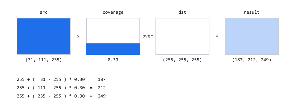
Figure 1. One boundary pixel: a blue source over white, at coverage 0.30.
Figure 1 is the arithmetic above, drawn. The destination is white, the source is the blue from our palette, the coverage is 0.30, and the result is the pale blue that Part 1 predicted. Note that the coverage panel in the middle is not a color — it is a quantity, the fraction of the pixel the shape reached.
The rest of the arithmeticThe three variables after the guard are the standard "over" formulation:
- sa — how much of the result the source owns, after coverage;
- da — how much alpha the destination already had;
- ia — 1 - sa, the share left over for whatever was underneath;
- oa — the output alpha, sa + da * ia. The source contributes its share outright; the destination contributes its own alpha, but only in the portion the source did not claim.
Each color channel is then the sum of two contributions — source weighted by sa, destination weighted by da * ia — divided by oa.
That division is the step people often forget. Without it, the result becomes premultiplied and translucent pixels render too dark. Since ResourceCreate with COLOR_FORMAT_ARGB_NORMALIZE expects straight ARGB, feeding it premultiplied values makes every translucent pixel render darker than it should, as if the whole panel had been dipped in black. Dividing through oa un-premultiplies, putting the color back into the format the rest of the library uses.Part 1 flagged this distinction and deferred it; this is the deferred half. A straight pixel stores color and alpha independently, so a half-transparent red is (128, 255, 0, 0). A pre-multiplied pixel stores the color already scaled, so the same red is (128, 128, 0, 0). Both conventions are in common use and both are correct; mixing them is what goes wrong.
The two early returns are not just optimizations. sa <= 0 returning dst untouched is what lets the rasterizer skip pixels a shape never reached without having to test them separately. And oa <= 0 guards the division: transparent over transparent has no color to divide out, and the mathematically correct answer is simply "still transparent".
The + 0.5 before each cast is rounding, for the reason Part 1 gave: MQL5 truncates on conversion, so without it a channel value of 187.9 becomes 187, and repeated blends drift steadily darker.
The rasterizer, second version
The structure of Fill is unchanged from Part 3: bounding box, walk rows, find crossings, sort them, sweep with the winding number. Two things differ. Spans accumulate into a coverage array instead of being painted directly, and each row is sampled N times instead of once.
//+------------------------------------------------------------------+
//| CCairoRasterizer                                                 |
//+------------------------------------------------------------------+
class CCairoRasterizer
  {
private:
   CCairoEdgeList    m_edges;        // edges of the path being filled
   double            m_coverage[];   // NEW: one accumulator per pixel column
   double            m_cross_x[];    // where this scanline crosses each edge
   int               m_cross_dir[];  // and in which direction

   bool              EnsureCapacity(const int width, const int edge_count);
   void              AddSpan(const double xa, const double xb, const double weight,
                             const int lo, const int hi);
   void              SortCrossings(const int n);

public:
                     CCairoRasterizer();

   void              Fill(CCairoPath &path, const uint argb, uint &buffer[],
                          const int width, const int height);
  };
m_coverage holds one double per pixel column, not per pixel. That is the memory trick that makes this affordable: we only ever work on one row at a time, so we only ever need one row's worth of accumulators. A 920-pixel-wide panel needs a 920-element array, about 7 KB, reused for every row of every shape for the lifetime of the program.
//+------------------------------------------------------------------+
//| Grow the scratch arrays if needed. They are never shrunk.        |
//|                                                                  |
//| Checked, for the reason Part 2 and Part 3 check their own: if    |
//| the memory is refused and the code carries on regardless, the    |
//| sweep below writes past the end of an array instead of failing   |
//| where the mistake actually is.                                   |
//+------------------------------------------------------------------+
bool CCairoRasterizer::EnsureCapacity(const int width, const int edge_count)
  {
//--- the coverage accumulator needs one slot per pixel column
   if(ArraySize(m_coverage) < width)
      if(ArrayResize(m_coverage, width) < width)
         return false;

   if(ArraySize(m_cross_x) < edge_count)
     {
      if(ArrayResize(m_cross_x,   edge_count) < edge_count)
         return false;
      if(ArrayResize(m_cross_dir, edge_count) < edge_count)
         return false;
     }

   return true;
  }
The return value is new in this part, and it follows the rule Part 2 and Part 3 already set: a refused ArrayResize is reported, not trusted. Without the check, a failed resize here would let the sweep below write past the end of m_coverage — a coverage array is exactly as capable of an out-of-range write as the point and edge arrays were, and there is no reason to guard those two and not this one. Note the shape of the test: the two crossing arrays are grown together, so the early exit looks at m_cross_x alone and assumes m_cross_dir followed it.
AddSpan: the exact fractionThis is the new function, and the whole point of Part 4.
//+------------------------------------------------------------------+
//| THE NEW FUNCTION, AND THE WHOLE POINT OF PART 4.                 |
//+------------------------------------------------------------------+
void CCairoRasterizer::AddSpan(const double xa, const double xb,
                               const double weight,
                               const int lo, const int hi)
  {
   double a = xa;
   double b = xb;

   if(b <= a)
      return;

//--- clip to the range of columns this shape can touch
   if(a < lo)
      a = lo;

   if(b > hi + 1)
      b = hi + 1;

   if(b <= a)
      return;

   const int ia = (int)MathFloor(a);

//--- THE EPSILON MATTERS. A span ending exactly on a pixel
//--- boundary, say at x = 14.0, covers NOTHING of column 14.
//--- Without the nudge, MathFloor(14.0) = 14 and we would add a
//--- zero-width contribution to a column the shape never reached
//--- - visible as a faint one-pixel fringe on every axis-aligned
//--- right-hand edge.
   const int ib = (int)MathFloor(b - 1e-9);

//--- the whole span lies inside a single pixel
   if(ia == ib)
     {
      m_coverage[ia] += weight * (b - a);
      return;
     }

   m_coverage[ia] += weight * ((ia + 1) - a);       // leading partial pixel

   for(int x = ia + 1; x < ib; x++)
      m_coverage[x] += weight;                     // fully covered interior

   m_coverage[ib] += weight * (b - ib);             // trailing partial pixel
  }
The span is a real-numbered interval, not a range of pixels. That single sentence is the difference between this article and the last one. Part 3 rounded the interval to whole pixels with MathRound and threw away everything the geometry knew about where the edge really was. Here, the first and last pixels a span touches receive only the fraction they are actually covered by, and every pixel fully inside receives the whole weight.
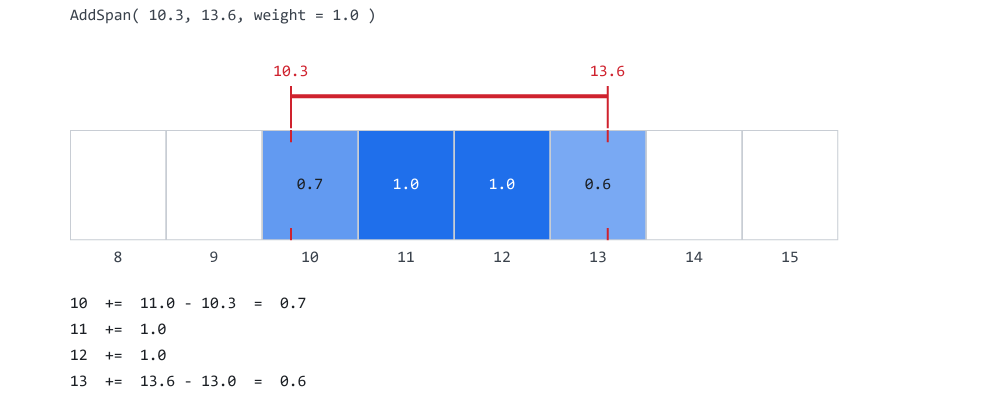
Figure 2. A span from 10.3 to 13.6, and the exact fraction each column is owed.
Figure 2 is the worked example. Column 10 is entered at 10.3 and runs to the column's end at 11.0, so it gets 0.7. Columns 11 and 12 are wholly inside, so they get 1.0 each. Column 13 is entered at its start and left at 13.6, so it gets 0.6. Three subtractions and a loop; no sampling anywhere in it.
Two details in that function are load-bearing.
The epsilon. MathFloor( b - 1e-9 ) rather than MathFloor( b ) looks like superstition, and it is not. Consider a span ending exactly on a pixel boundary, at x = 14.0 — which happens constantly, because axis-aligned rectangles are the most common shape in any interface. MathFloor( 14.0 ) is 14, so the trailing line would execute m_coverage[14] += weight * ( 14.0 - 14 ), crediting a column the shape never reached. The contribution is zero, so nothing looks wrong — until the span ends on the last column the shape may touch. b is clamped to hi + 1 just above, so without the nudge ib becomes hi + 1, and with hi at width - 1 the trailing line writes m_coverage[width]: one slot past the end of the accumulator, which in MQL5 is an array-out-of-range error that stops the program. The nudge makes ib land on the last real column instead, where it belongs.
The weight parameter. It is 1 / CairoAaSamples, so that the N sub-scanlines of one row sum to at most 1.0. The accumulator is shared across all N passes over the row, which is exactly what makes averaging in Y free — no separate buffer, no second pass, just N contributions landing in the same slots.
Fill: two guards, then the sweepFill itself opens with the two checks the rest of this section assumes:
//+------------------------------------------------------------------+
//| Fill `path` with the color `argb` into an ARGB buffer.           |
//+------------------------------------------------------------------+
void CCairoRasterizer::Fill(CCairoPath &path, const uint argb,
                            uint &buffer[],
                            const int width, const int height)
  {
//--- a path that lost an allocation is not geometry we can trust
   if(!path.IsValid())
      return;

   path.BuildEdges(m_edges);

   const int edge_count = m_edges.m_count;

   if(edge_count == 0)
      return;

   if(!EnsureCapacity(width, edge_count))
      return;                        // no scratch room - draw nothing
Both checks are refusals, not error handling in the usual sense — there is nowhere for Fill() to report a problem to, so the honest response to "the path is broken" or "the buffer could not be grown" is to draw nothing rather than draw something wrong. path.IsValid() is the same flag Part 2 introduced for exactly this: a CCairoPath that lost an allocation while it was being built remembers that it did, so every consumer of the path can ask once instead of guessing from a possibly-truncated vertex count. EnsureCapacity() returning bool is the same idea one level down, applied to the rasterizer's own scratch memory. What Fill() does not check is the buffer, so the caller must pass one of at least width * height elements.
Neither check changes what a correctly-built path does. Both exist for the path that a division by zero, a bad input or an out-of-memory condition already damaged before it reached this function — the case where silently continuing would draw a shape that looks plausible and is wrong.
The bounding box, now in both axes//--- BOUNDING BOX, now in BOTH axes. //--- //--- Part 3 only needed the vertical extent, to know which rows to //--- walk. Now we also need the horizontal extent, because the //--- coverage accumulator has to be cleared before each row - and //--- clearing the whole buffer width for a 20-pixel-wide shape //--- would cost far more than drawing it. //--- //--- An edge is a straight segment, so its x extremes are at its //--- two ends; there is no need to walk along it. double ymin = 1e18, ymax = -1e18; double xmin = 1e18, xmax = -1e18; for(int i = 0; i < edge_count; i++) { const double etop = m_edges.m_edges[i].ytop; const double ebot = m_edges.m_edges[i].ybot; if(etop < ymin) ymin = etop; if(ebot > ymax) ymax = ebot; const double xa = m_edges.m_edges[i].xtop; const double xb = m_edges.m_edges[i].XAt(ebot); if(xa < xmin) xmin = xa; if(xb < xmin) xmin = xb; if(xa > xmax) xmax = xa; if(xb > xmax) xmax = xb; }
Part 3 needed only the vertical extent, to know which rows to walk. Now the horizontal extent is needed too, because the coverage accumulator has to be cleared before each row — and clearing 920 columns to draw a 20-pixel-wide shape would cost far more than drawing it.
An edge is a straight segment, so its x extremes are at its two ends; there is no need to walk along it. xtop is one end by construction, and XAt( ebot ) gives the other.
   int iy0 = (int)MathFloor(ymin);
   int iy1 = (int)MathCeil(ymax);
   int ix0 = (int)MathFloor(xmin);
   int ix1 = (int)MathCeil(xmax);

   if(iy0 < 0)
      iy0 = 0;
   if(iy1 > height)
      iy1 = height;
   if(ix0 < 0)
      ix0 = 0;
   if(ix1 > width - 1)
      ix1 = width - 1;

//--- entirely off the buffer
   if(ix1 < ix0 || iy1 <= iy0)
      return;
Note the asymmetry in the clamps: iy1 is clamped to height because the row loop is iy < iy1, while ix1 is clamped to width - 1 because the column loops are inclusive, x <= ix1. Getting that wrong writes one pixel past the end of a row, which in MQL5 is an array-out-of-range error that stops the program.
N sub-scanlines per row//--- How finely do we sample the row vertically? int samples = CairoAaSamples; if(samples < 1) samples = 1; const double weight = 1.0 / samples; //--- WALK THE ROWS for(int iy = iy0; iy < iy1; iy++) { //--- clear only the columns this shape can possibly touch for(int x = ix0; x <= ix1; x++) m_coverage[x] = 0.0; //--- N SUB-SCANLINES PER ROW. //--- //--- Part 3 took one sample, at iy + 0.5. Now we take N, spread //--- evenly through the row, each contributing 1/N of the //--- coverage. //--- //--- This is what fixes a NEAR-HORIZONTAL edge. Consider a line //--- at a very shallow angle crossing a row: with one sample //--- the row is either fully in or fully out, so the edge //--- advances in whole-row jumps. With four, a row can be 25%, //--- 50% or 75% covered, and the jump is smoothed away. for(int s = 0; s < samples; s++) { //--- center of each sub-row, never its boundary const double yc = iy + (s + 0.5) / samples;
The clamp on samples guards against a caller setting the global to zero or a negative, which would make weight infinite or the loop never run. There is no guard at the top end, so a caller who asks for a thousand samples gets a fill that is a thousand times slower. A library that exposes a global for tuning has to assume the global will eventually hold something silly.
( s + 0.5 ) / samples puts each sub-scanline at the center of its slice, never on a boundary — the same reasoning as Part 3's iy + 0.5, applied one level down. With samples = 4 the sample lines sit at 0.125, 0.375, 0.625 and 0.875 of the way down the row.
This is what fixes a near-horizontal edge. Consider a line at a very shallow angle crossing a row: with one sample the row is either fully in or fully out, so the edge advances in whole-row jumps and the shape bands. With four, a row can be 25%, 50% or 75% covered, and the jump is smoothed away.
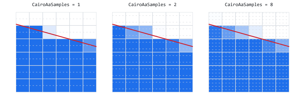
Figure 3. The same shallow edge at one, two and eight samples per row.
Figure 3 isolates that case, and it is computed by running the same arithmetic the rasterizer runs. At one sample the shallow edge advances in whole rows, and the banding is obvious. At two it is halved. At eight the boundary carries a smooth gradient of partial values. The faint dashed lines are the sub-scanlines each row was cut into — count them, and the setting stops being abstract.
This figure also shows why the default is 4 rather than 16. The step from 1 to 2 is dramatic, from 2 to 4 clear, and from 4 to 8 barely visible at screen resolution — while the cost keeps rising in a straight line.
Finding crossings, and accumulatingint n = 0; for(int i = 0; i < edge_count; i++) { //--- half-open [ytop, ybot), exactly as in Part 3: a //--- vertex shared by two edges counts exactly once if(yc >= m_edges.m_edges[i].ytop && yc < m_edges.m_edges[i].ybot) { m_cross_x[n] = m_edges.m_edges[i].XAt(yc); m_cross_dir[n] = m_edges.m_edges[i].dir; n++; } } if(n < 2) continue; SortCrossings(n); //--- sweep with the winding number, as before - but a span //--- is now ACCUMULATED rather than painted int winding = 0; for(int k = 0; k < n - 1; k++) { winding += m_cross_dir[k]; if(winding != 0) AddSpan(m_cross_x[k], m_cross_x[k + 1], weight, ix0, ix1); } }
Compare this with Part 3 and the only changed line is the last one. The half-open crossing test, the insertion sort, the winding number: all identical, all doing exactly what they did before. AddSpan has replaced the rounding and the direct write, and nothing else about the sweep needed to know.
That is worth pausing on, because it is a sign the Part 3 design was right. A change this visible — every edge in the library going from jagged to smooth — touched one line of the algorithm and added one function.
Compositing the finished row//--- COMPOSITE THE FINISHED ROW. //--- //--- Every column now holds a number from 0 to 1: how much of //--- that pixel the shape covers. Hand it to CairoBlendOver and //--- the anti-aliasing happens for free, because coverage and //--- alpha are the same thing. const int row_base = iy * width; for(int x = ix0; x <= ix1; x++) { double a = m_coverage[x]; //--- untouched pixel: leave the destination alone. This is //--- what stops a shape disturbing anything outside itself, //--- even within its own bounding box. if(a <= 0.0) continue; //--- Sub-spans that overlap within one sub-scanline can //--- push the sum slightly past 1.0 - a self-overlapping //--- path does exactly that. Clamp, rather than letting a //--- coverage of 1.3 brighten the pixel. if(a > 1.0) a = 1.0; const int idx = row_base + x; buffer[idx] = CairoBlendOver(buffer[idx], argb, a); } } }
Every column now holds a number from 0 to 1: how much of that pixel the shape covers. Hand it to CairoBlendOver() and the anti-aliasing happens for free.
The a <= 0.0 skip is what stops a shape disturbing anything outside itself, even within its own bounding box. A thin diagonal line has a large bounding box and touches very few of the pixels in it; without this test every one of those pixels would be composited with coverage zero — correct in result, wasteful in time.
The clamp above 1.0 is a safety net against arithmetic, not against geometry. The spans of one sub-scanline come from the sorted crossings, so they are consecutive and never overlap, however many contours the path has and however they cross: every crossing goes into the same sorted list, and the sweep hands out disjoint intervals. Each sub-scanline therefore adds at most weight to a column, and N of them sum to at most 1.0. What the clamp catches is a sum that lands on 1.0000000002 after N floating-point additions, which would otherwise reach CairoBlendOver as a coverage above 1 — a value that function trusts rather than checks.
The demo
Demo04_AntiAliasing.mq5 is six panels, each isolating one consequence.
A — the Part 3 fan, redrawn. Byte for byte the same geometry as Part 3's staircase row:
//+------------------------------------------------------------------+
//| A. THE PART 3 FAN, REDRAWN                                       |
//+------------------------------------------------------------------+
void PanelFan(const double ox, const double oy)
  {
   for(int i = 0; i < 7; i++)
     {
      const double a = -M_PI * 0.5 + M_PI * 0.5 * i / 6.0;

      CCairoPath t;
      t.AddTriangle(ox, oy + 120,
                    ox + 150 * MathCos(a),
                    oy + 120 + 150 * MathSin(a),
                    ox + 150 * MathCos(a + 0.09),
                    oy + 120 + 150 * MathSin(a + 0.09));

      Fill(t, CairoLerp(C_BLUE, C_ORANGE, i / 6.0));
     }
  }
Not one number in that function changed. Only the rasterizer underneath it did. Put this screenshot beside Part 3's at the same magnification and the comparison is the entire argument of this article.
B — the quality dial. The same star at four settings, timed. The span length on each sub-scanline is exact in X whatever the setting, so the visible difference here is confined to the star's shallower edges — panel D isolates that case deliberately. What this panel is for is the price of the dial:
//+------------------------------------------------------------------+
//| B. THE QUALITY DIAL                                              |
//+------------------------------------------------------------------+
void PanelSamples(const double ox, const double oy)
  {
   const int saved = CairoAaSamples;

   int levels[4] = { 1, 2, 4, 8 };

   for(int k = 0; k < 4; k++)
     {
      CairoAaSamples = levels[k];

      const double cx = ox + k * 150;

      double xs[10], ys[10];

      for(int i = 0; i < 10; i++)
        {
         const double r = (i % 2 == 0) ? 58.0 : 24.0;
         const double a = -M_PI * 0.5 + M_PI * i / 5.0;

         xs[i] = cx + 62 + r * MathCos(a);
         ys[i] = oy + 62 + r * MathSin(a);
        }

      CCairoPath star;
      star.AddPolygon(xs, ys, 10);

      //--- the one fill the reader sees
      Fill(star, C_ORANGE);

      //--- an untimed warm-up so the scratch arrays are already at
      //--- their high-water mark, then 40 timed repeats - all of
      //--- them invisible, see the note above
      Fill(star, C_NONE);

      const ulong t0 = GetMicrosecondCount();

      for(int r2 = 0; r2 < 40; r2++)
         Fill(star, C_NONE);

      const ulong t1 = GetMicrosecondCount();

      PrintFormat("B. CairoAaSamples = %d  ->  %.1f us per fill",
                  levels[k], (double)(t1 - t0) / 40.0);
     }

   CairoAaSamples = saved;
  }
The warm-up fill matters. The first fill of any shape grows the scratch arrays to their high-water mark, so timing it would measure allocation rather than rasterizing. Forty repeats then average away the noise from whatever else the terminal is doing.
The C_NONE in those repeats matters more, and it is worth dwelling on because getting it wrong produces a bug that looks like a rasterizer fault and is not one. Fill composites; it does not overwrite. Drawing the same opaque star forty times to time it therefore does not draw it forty times identically — it blends it onto itself. A pixel at coverage a after n fills ends up at 1 - (1 - a)^n, and that expression climbs to 1 alarmingly fast:
coverage after 1 fill    after 41 fills
    0.94                     1.000
    0.67                     1.000
    0.40                     1.000
    0.14                     0.998
    0.004                    0.148
Every partial pixel along every edge — the entire subject of this article — is driven to solid by the act of measuring it, and the panel comes out looking exactly like the hard yes/no fill of Part 3. The benchmark would be destroying the thing it was put there to demonstrate.
C_NONE is CairoArgb( 0, 0, 0, 0 ): alpha zero. CairoBlendOver returns dst untouched the moment sa <= 0, so a fill in that color builds the edge list, walks the rows, takes every sub-scanline sample and accumulates all the coverage — and then writes nothing. Be clear about what that leaves out: the same early return also skips the blend arithmetic, so a visible fill costs a little more than these numbers say. Everything that scales with the sample count is measured; the final per-pixel blend is not.
The panel saves and restores the global rather than leaving it changed:
    const int saved = CairoAaSamples;
    ...
    CairoAaSamples = saved;
C — sub-pixel positioning is real now. Ten identical bars, each shifted a further tenth of a pixel:
//+------------------------------------------------------------------+
//| C. SUB-PIXEL POSITIONING IS REAL NOW                             |
//+------------------------------------------------------------------+
void PanelSubPixel(const double ox, const double oy)
  {
   for(int i = 0; i < 10; i++)
     {
      CCairoPath bar;
      bar.AddRect(ox + i * 34 + i / 10.0, oy, 22, 90);
      Fill(bar, C_GREEN);
     }
This is the third time the series has drawn this experiment, and the first time it works. In Part 2 the path stored the offsets faithfully and the crude plotter rounded them away. In Part 3 the rasterizer rounded them away. Here they survive all the way to the screen: each bar's left edge is shaded a slightly different strength, and the bars creep rightwards in tenth-pixel steps that are visible to the eye.
That is what makes smooth animation possible. A widget moving 0.1 px per frame now glides instead of juddering between whole pixels.
The panel then draws hairlines at fractional widths:
//--- and a single hairline at a series of fractional widths, to
//--- show that a shape THINNER than a pixel still renders - it
//--- simply comes out fainter, which is exactly right
   for(int i = 0; i < 10; i++)
     {
      CCairoPath hair;
      hair.AddRect(ox + i * 34 + 22, oy + 100, i / 10.0, 60);
      Fill(hair, C_BLUE);
     }
  }
A rectangle 0.1 pixels wide still renders. It comes out faint rather than missing, because its coverage is 0.1 and CairoBlendOver() mixes it in at that strength — which is exactly right, and is what a real renderer does. Part 3 would have drawn nothing at all for the first nine of these.
D — where sampling in Y matters. Very shallow wedges, almost horizontal:
//+------------------------------------------------------------------+
//| D. WHERE SAMPLING IN Y ACTUALLY MATTERS                          |
//+------------------------------------------------------------------+
void PanelShallow(const double ox, const double oy)
  {
   for(int i = 0; i < 5; i++)
     {
      const double y = oy + i * 30;

      CCairoPath wedge;
      wedge.AddTriangle(ox, y,
                        ox + 380, y + 2.0 + i * 1.5,
                        ox + 380, y + 16);
      Fill(wedge, CairoLerp(C_PURPLE, C_GREEN, i / 4.0));
     }
  }
Set CairoAaSamples to 1 and this panel bands visibly; set it to 8 and it is smooth. Everything else in the demo looks near-identical at either setting, which is the practical lesson: the dial only buys you anything on near-horizontal edges.
E — compositing. Three overlapping translucent discs:
//+------------------------------------------------------------------+
//| E. COMPOSITING                                                   |
//+------------------------------------------------------------------+
void PanelBlending(const double ox, const double oy)
  {
   const int n = 120;

   double cx[3], cy[3];
   uint   cols[3];

   cx[0] = ox + 70;
   cy[0] = oy + 60;
   cols[0] = C_RED;
   cx[1] = ox + 130;
   cy[1] = oy + 60;
   cols[1] = C_GREEN;
   cx[2] = ox + 100;
   cy[2] = oy + 110;
   cols[2] = C_BLUE;

   for(int k = 0; k < 3; k++)
     {
      double xs[], ys[];

      ArrayResize(xs, n);
      ArrayResize(ys, n);

      for(int i = 0; i < n; i++)
        {
         const double a = 2.0 * M_PI * i / n;

         xs[i] = cx[k] + 52 * MathCos(a);
         ys[i] = cy[k] + 52 * MathSin(a);
        }

      CCairoPath disc;
      disc.AddPolygon(xs, ys, n);

      Fill(disc, CairoWithOpacity(cols[k], 0.55));
     }
  }
Part 3 would have drawn three flat discs, each wiping out the one before. Where two overlap the color is now the correct blend of both; where three overlap, of all three. Look closely at where the anti-aliased boundaries cross each other: they stay clean, with no dark seam. That is the straight-alpha arithmetic in CairoBlendOver() doing its job, and it is the visible symptom that would appear if the un-pre-multiply step were missing.
F — a coverage ramp. The same bar at ten opacities, over a checkerboard drawn with the rasterizer itself:
//+------------------------------------------------------------------+
//| F. A COVERAGE RAMP                                               |
//+------------------------------------------------------------------+
void PanelRamp(const double ox, const double oy)
  {
//--- checkerboard background
   for(int r = 0; r < 8; r++)
      for(int c = 0; c < 40; c++)
        {
         if((r + c) % 2 != 0)
            continue;

         CCairoPath sq;
         sq.AddRect(ox + c * 9, oy + r * 9, 9, 9);
         Fill(sq, CairoRgb(231, 235, 239));
        }

   for(int i = 0; i < 10; i++)
     {
      CCairoPath bar;
      bar.AddRect(ox + i * 36, oy, 30, 72);
      Fill(bar, CairoWithOpacity(C_ORANGE, 1.0 - i / 10.0));
     }
  }
coverage and alpha enter CairoBlendOver() through the same multiplication, so a 50%-covered pixel of an opaque color and a fully covered pixel of a 50% color produce the identical result. This panel is that claim, made checkable: the faded bars here are the same values that appear along every anti-aliased edge elsewhere in the demo.
What to look at 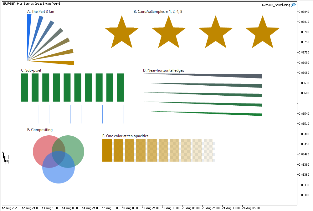
Figure 4. Demo04_AntiAliasing on a Black On White chart: six panels, one call.
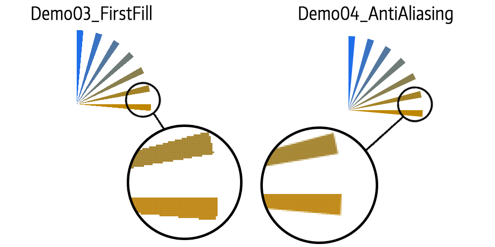
Figure 5. The same fan from Part 3 and Part 4, magnified without interpolation.
Figure 5 is the one that matters, and it is worth being precise about what to look at. Do not look at the shapes; they are identical. Look at the boundary pixels. On the left there are two values in the picture — full color and full background. On the right there are perhaps a dozen, all of them along the edge, and the interior and exterior are untouched. That is where the new values are: anti-aliasing produces partial values only where a boundary crosses a pixel, which for a typical panel is a small fraction of the total. The work is spread wider than the values are — every covered row is sampled N times, and every pixel the shape reaches is composited.
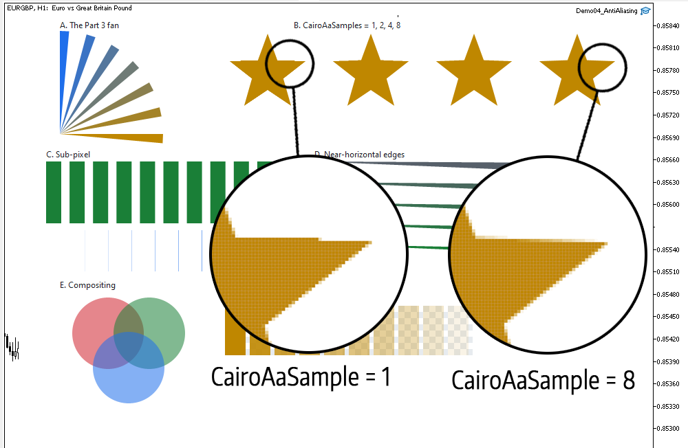
Figure 6. Compare the different values of CairoAaSamples
Simply in Figure 6, we can see how CairoAaSamples affects shape smoothing. As shown, edges that are near-horizontal show a stronger effect; on steeper edges, sampling has less effect.
The log reports the quality dial's price:
=== Part 4: coverage instead of a yes/no test ===
B. CairoAaSamples = 1  ->  194.2 us per fill
B. CairoAaSamples = 2  ->  227.8 us per fill
B. CairoAaSamples = 4  ->  305.5 us per fill
B. CairoAaSamples = 8  ->  440.5 us per fill
whole 940x700 frame in 62849 us at CairoAaSamples = 4
Your numbers will differ, but the shape of them will not: the cost is close to linear in the sample count, with a fixed overhead — building edges, clearing the accumulator, compositing the row — that does not scale with it. That fixed part is why 2 samples cost less than twice 1.
Project structure
Extract the archive under MQL5/, preserve the folder structure, and compile Demo04_AntiAliasing.mq5. No paths need editing.
MQL5/
├── Include/
│   └── CairoG2D/
│       ├── Color.mqh          // the ARGB color type, and now blending
│       ├── Config.mqh         // CairoAaSamples - the quality dial
│       ├── Surface.mqh        // pixel buffer bound to one chart object
│       ├── Path.mqh           // the path and the edges - unchanged this part
│       ├── Raster.mqh         // the scanline fill, now with coverage
│       └── DemoTheme.mqh      // the demos' shared palette - NOT library code
└── Experts/
    └── CairoG2D/
        └── Article 04/
└── Demo04_AntiAliasing.mq5 // six panels, one Fill() | # | File | Directory | Holds |
|---|---|---|---|
| 1 | Color.mqh | MQL5/Include/CairoG2D | the ARGB color type, and now CairoBlendOver |
| 2 | Config.mqh | MQL5/Include/CairoG2D | CairoAaSamples, and the version string |
| 3 | Surface.mqh | MQL5/Include/CairoG2D | CCairoSurface - pixel buffer to chart bitmap |
| 4 | Path.mqh | MQL5/Include/CairoG2D | the path, SCairoEdge and BuildEdges |
| 5 | Raster.mqh | MQL5/Include/CairoG2D | CCairoRasterizer - coverage and compositing |
| 6 | DemoTheme.mqh | MQL5/Include/CairoG2D | palette, chart setup, captions - not library code |
| 7 | Demo04_AntiAliasing.mq5 | MQL5/Experts/CairoG2D/Article 04 | six panels, and the timed quality dial |
| 8 | Cairo-Style Library - Part 04.zip | archive containing all the attached files and their paths relative to the terminal's root folder. |
Two earlier files changed this part. Color.mqh gained CairoBlendOver at the bottom, with nothing above it touched. Raster.mqh gained m_coverage, AddSpan, the horizontal bounding box, the sub-scanline loop, and the checked EnsureCapacity return; its four-step structure is the same one Part 3 explained. Path.mqh and Surface.mqh were not touched at all.
Conclusion, and what comes next
The engine now renders the way a modern 2D library renders. Edges are smooth at any angle, shapes can sit at fractional positions and move by fractions of a pixel, translucent colors composite correctly over whatever is beneath them, and a shape narrower than a pixel renders faintly instead of vanishing. A shape that is thin the other way, shorter than a pixel, depends on the sample count: it is missed when no sub-scanline falls inside it.
All of that came from replacing one question with another. The pieces:
- coverage — the fraction of a pixel a shape actually covers, computed exactly in X by subtraction and approximated in Y by N sub-scanlines;
- AddSpan — which credits partial pixels at each end of a span instead of rounding the span to whole pixels;
- CairoBlendOver — the over operator on straight ARGB, which takes coverage through the same multiplication as alpha and therefore implements anti-aliasing without a line of code named after it;
- CairoAaSamples — one runtime dial, with a measured price.
What is still missing is a way to say what "inside" means. Today there is one answer, the non-zero rule inherited from Part 3, and it is why the letter A in Part 3's demo filled solid unless the caller reversed the counter's vertex order by hand. Asking every caller to think about winding direction is not a library; it is a trap.
Later we add the even-odd fill rule and let the caller choose. With it, a path containing two nested contours becomes a ring, a frame or a letter with a proper hole, without anyone reasoning about which way round the inner outline was traced. We will look at exactly when the two rules disagree, and why fonts and SVG each prefer a different one.
Then, with holes available, we build strokes out of fills: an outline plus an inset copy of itself is a border of any thickness, and the same machinery gives rings, donut charts and the frames every panel is made of. It is where the library starts to look like something you would build an interface with.
The project is supported on MQL5 Algo Forge. Each part of this series has its own release, frozen at exactly the code that part explains, so whichever article you are reading, its release is the one to download.
Part 4 is here: https://forge.mql5.io/SandroBegashvil/CairoG2D/releases/tag/part-04
Warning: All rights to these materials are reserved by MetaQuotes Ltd. Copying or reprinting of these materials in whole or in part is prohibited.
This article was written by a user of the site and reflects their personal views. MetaQuotes Ltd is not responsible for the accuracy of the information presented, nor for any consequences resulting from the use of the solutions, strategies or recommendations described.

 Building a Neural Loss-Pattern Auditor in MQL5
 Creating a Cairo-Inspired Graphics Library for MetaTrader 5 (Part 3): Edges and the First Filled Shape
 Features of Experts Advisors
 Random Matrix Theory: Denoising the Correlation Matrix for Multi-Symbol EAs

- Free trading apps
- Over 8,000 signals for copying
- Economic news for exploring financial markets
You agree to website policy and terms of use