DirectX Tutorial (Part I): Drawing the first triangle
Rorschach | 21 April, 2022
Table of contents
- Introduction
- DirectX API
- Graphics Pipeline
- 3D Graphics
- Sequence of Actions in MQL
- Practice
- Class Overview
- Vertex Array
- Initialization
- Creating a Canvas
- DirectX Initialization
- Image Display
- Releasing Resources
- Shaders
- OnStart
- Conclusion
- References and Links
Introduction
An initiation rite, or initialization rite is what comes to mind when you understand that you have to write so much code and fill huge C++ structures, to draw even a primitive triangle using DirectX. Not to mention more complex things, such as textures, transformation matrices and shadows. Fortunately, MetaQuotes took care of this: they hid the whole routine, while leaving only the most necessary functions. However, there is a side effect of this: anyone not previously familiar with DirectX cannot see the whole picture and understand why and how it is all happening. There is still much code to be written in MQL.
Without understanding what is there under the hood, DirectX is perplexing: "Why is it so difficult and confusing, can't it be made simpler?" And this is only the first stage. Further, you come to study the HLSL shader language and the peculiarities of video card programming. In order to avoid all these confusions, I suggest considering the internal structure of DirectX, though not going too deep into detail. Then we will write a small script in MQL that displays a triangle on the screen.
DirectX API
History of DirectX
DirectX is a set of APIs (Application Programming Interface) for working with multimedia and video on Microsoft platforms. It was primarily developed for creating games, but over time developers started to use it in engineering and mathematical software. DirectX allows working with graphics, sound, inputs and networks without the need to access low-level functions. The API appeared as an alternative to the cross-platform OpenGL. When creating Windows 95, Microsoft implemented substantial changes, which made the environment more difficult to develop applications and games and thus could affect the popularity of this operating system. DirectX was created as a solution to get more programmers to develop games for Windows. DirectX development was started by Craig Eisler, Alex St. John and Eric Engstrom.
- September 1995. First release. It was a rather primitive version, which ran as an add-on to the Windows API. It didn't get much attention. Developers were mostly using DOS, compared to which the new OS had higher system requirements. In addition, OpenGL already existed by that time. It was not clear whether Microsoft would continue to support DirectX.
- June 1996. The release of version 2.
- September 1996. Version 3.
- August 1997. Instead of the fourth version Microsoft released version 5. It became easier to write code with this version, and programmers started to pay attention to it.
- August 1998. Version 6. The work was further simplified.
- September 1999. Version 7. It became possible to create vertex buffers in video memory which as a big advantage over OpenGL.
- November 2000. Version 8. Crucial moment. Before this moment, DirectX was trying to catch up, but version eight overtook the industry. Microsoft began to cooperate with graphics card manufacturers. Vertex and pixel shaders appeared. The development required only a personal computer, unlike OpenGL which required a workstation.
- December 2002. Version 9. DirectX has become the industry standard. HLSL shader language appeared. Probably this was the longest-lived version of DirectX. Like socket 775...
- November 2006. Version 10. Unlike version 9, this one had a binding to the Vista operating system, which was not popular. These factors had a negative effect on the success of version 10. Microsoft added a geometry shader.
- October 2009. Version 11. Added tessellation, compute shader, improved work with multi-core processors.
- July 2015. Version 12. Low level API. The version provided an even better compatibility with multi-core processors, the ability to combine the resources of several video cards from different vendors, ray tracing.
Direct3D
Direct3D is one of many components of the larger DirectX API; it is responsible for graphics and is an intermediary between applications and the graphics card driver. Direct3D is based on COM (Component Object Model). COM is an application binary interface (ABI) standard introduced by Microsoft in 1993. It is used to create objects in inter-process communication (IPC) in various programming languages. COM appeared as a solution aiming to provide a language-independent way to implement objects that could be used outside of their creation environment. COM allows objects to be reused without knowing their internal implementation, because they provide well defined interfaces which are separate from the implementation. COM objects are responsible for their own creation and destruction using reference counting.
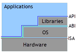
Interfaces
Device
Everything in Direct3D starts with Device. It is used to create resources (buffers, texture, shaders, state objects) and the enumeration of capabilities of graphics adapters. Device is a virtual adapter located on the user's system. The adapter can be either a real video card or its software emulation. Hardware devices are used most often because they provide the highest performance. Device provides a unified interface o all of these adapters and uses them to render graphics to one or more outputs.
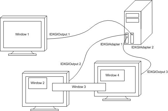
Device
Device Context
Device Context is responsible for anything related to rendering. This includes the pipeline configuration and the creation of commands for rendering. Device Context appeared in the eleventh version of DirectX — priorly rendering was implemented by Device. There are two types of context: Immediate Context and Deferred Context.
Immediate context provides access to data on the video card and the ability to immediately execute a command list on the device. Each Device has only one Immediate Context. Only one thread can access it at a time. Synchronization should be used to enable access for multiple threads.
Deferred Context adds commands to the command list to be executed later on the Immediate Context. Thus, all commands eventually pass through the Immediate Context. Deferred Context involves some overhead, so the benefits of using it are visible only when parallelizing resource-intensive tasks. You can create multiple Deferred Contexts and access each from a separate thread. But to access the same Deferred Context from multiple threads you need synchronization, just like with the Immediate Context.
Swap Chain
Swap Chain is designed to create one or more back buffers. These buffers store rendered images until they are displayed on the screen. The front and the back buffers operate as follows. The front buffer is what you on the screen. The back buffer is the image that is rendered to. Then the buffers are swapped: front one becomes back, and the back one comes to the front. And the whole process is repeated over and over again. Thus, we always see the picture, while the next one is being rendered "behind the scenes".
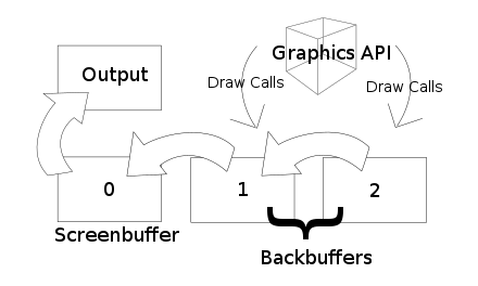
Swap Chain
Device, Device Context and Swap Chain are the main components needed to render an image.
Input Layout
The Input Layout informs the pipeline about the structure of the vertex buffer. We only need coordinates for our purposes, which is why we can simply pass the array of vertices of type float4, without using a special structure. float4 is a structure consisting of four float variables.
struct float4
  {
   float x;
   float y;
   float z;
   float w;
  };
For example, consider a more complex vertex structure consisting of a coordinate and two colors:
struct Vertex
  {
   float4 Pos;
   float4 Color0;
   float4 Color1;
  };
Input layout in MQL for this structure will look like this:
DXVertexLayout layout[3] = {{"POSITION", 0, DX_FORMAT_R32G32B32A32_FLOAT},
                            {"COLOR", 0, DX_FORMAT_R32G32B32A32_FLOAT},
                            {"COLOR", 1, DX_FORMAT_R32G32B32A32_FLOAT}};
Each element of the 'layout' array describes the corresponding element of the Vertex structure.
- The first element of the structure DXVertexLayout is the semantic name. It is used to map the elements of the Vertex structure with the elements of the structure in the vertex shader. "POSITION" means that the value is responsible for the coordinates, "COLOR" is used for the color.
- The second element is the semantic index. If we need to pass several parameters of the same type, for example, two color values, the first one is passed with index 0 and the second one with index 1.
- The last element describes the type in which the value is represented in the Vertex structure. DX_FORMAT_R32G32B32A32_FLOAT literally means that it is an RGBA color represented by a 32-bit floating point value for each component. This can be confusing. This type can be used to pass coordinates — it provides information about four 32-bit floating point values, just like float4 in the Vertex structure.
Primitive Topology
The vertex buffer stores information about the points, but we do not know how they are located relative to each other in the primitive. This is what Primitive Topology is used for. Point List means that the buffer stores individual points. Line Strip represents the buffer as connected points forming a polyline. Every two points in the Line List describe one single line. Triangle Strip and Triangle List set the order of points for triangles, similar to lines.
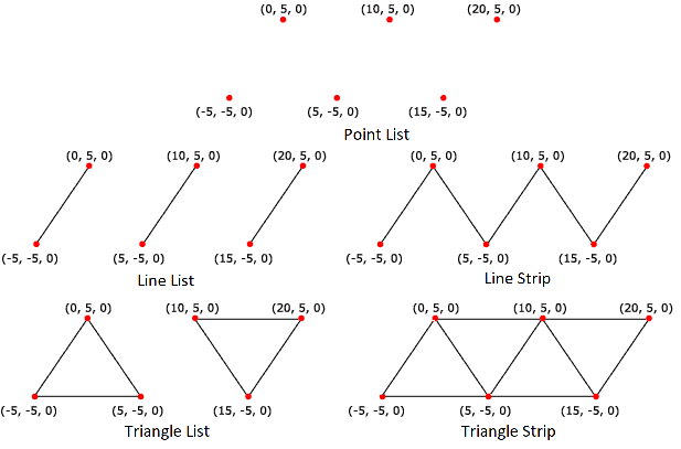
Topology
HLSL
High Level Shading Language (HLSL) is a C-like language for writing shaders. Shaders, in turn, are programs designed to run on a graphics card. Programming in all GPGPU languages is very similar and has a specific feature related to the design of graphics cards. If you have experience with OpenCL, Cuda, or OpenGL you will understand HLSL very quickly. But if you only created programs for CPUs, then it may be difficult to switch to a new paradigm. Often, the optimization methods traditionally used for the processor will not work. As an example, it would be correct for the processor to use the 'if' statement to avoid unnecessary calculations or to select the optimal algorithm. But on the GPU, on the contrary, this can increase the program execution time. To take the maximum, you may have to count the number of involved registers. The three main principles of high performance when programming graphics cards are: parallelism, throughput and occupancy.
Graphics Pipeline
The pipeline is designed to convert a 3D scene into a 2D display representation. The pipeline is a reflection of the internal structure of the video card. The diagram below shows how the data stream flows from the pipeline input to its output through all stages. The oval shows stages that are programmed using the HLSL language — shaders, and the rectangle shows fixed stages. Some of them are optional and can be easily skipped.
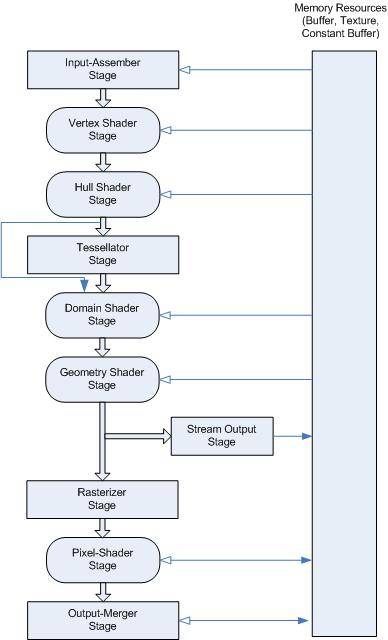
Graphics Pipeline
-
Input Assembler stage receives data from the vertex and index buffers and prepares it for the vertex shader.
- Vertex Shader stage performs operations with vertices. Programmable stage. Mandatory in the pipeline.
- Hull Shader stage is responsible for the level of tessellation. Programmable stage. Optional.
- Tessellator stage creates smaller primitives. Fixed stage. Optional.
- Domain Shader stage computes the final vertex values after tessellation. Programmable stage. Optional.
- Geometry Shader stage applies various transformations to primitives (points, lines, triangles). Programmable stage. Optional.
- Stream Output stage transfers data to the GPU memory from which they can be sent back to the pipeline. Fixed stage. Optional.
- Rasterizer stage cuts off everything that does not fall into the scope, prepares data for the Pixel shader. Fixed stage.
-
Pixel Shader stage performs pixel operations. Programmable stage. Mandatory in the pipeline.
- Output Merger stage forms the final image. Fixed stage.
Another shader is worth mentioning is Compute Shader (DirectCompute), which is a separate pipeline. This shader is designed for general purpose calculations, similar to OpenCL and Cuda. Programmable stage. Optional.
MetaQuotes' implementation of DirectX does not include DirectCompute and the tessellation stage. Thus, we have only three shaders: vertex, geometry and pixel.
3D Graphics
Primitives
Rendering primitives is the primary purpose of the graphics API. Modern video cards are adapted for quick rendering of a large number of triangles. Actually, at the current computer graphics development stage, the most effective way to draw 3D objects is to create a surface from polygons. A surface can be described by specifying only three points. 3D modeling software often use rectangles, but the graphics card will still force the polygons into triangles.

Mesh of triangles
Vertexes
Three vertices must be specified to render a triangle in Direct3D. It may seem that a vertex is the position of a point in space, but in Direct3D it is something more than that. In addition to the vertex position, we can pass color, texture coordinates, normals. Generally, matrix transformations are usually used to normalize coordinates. In order not to complicate it at this moment, take into account the fact that at the stage of rasterization the coordinates of the vertices along the X and Y axes must be within [-1; 1]; along Z - from 0 to 1.
Color
Color in computer graphics has three components: red, green and blue. This is related to the structural features of the human eye. Display pixels also consist of three sub-pixels of these colors. MQL has the ColorToARGB function to convert web colors to the ARGB format which store transparency in addition to the color. The color can be normalized when the components are in the range [0;1], and unnormalized: for example, components for a 32-bit color will have values from 0 to 255 (2^8-1). Most modern displays work with 32-bit color.
Sequence of Actions in MQL
To display an image using DirectX in MQL, you need to do the following:
- Create a Bitmap Label or Bitmap object using ObjectCreate.
- Create a dynamic graphical resource using ResourceCreate.
- Link a resource to the object using ObjectSetString with the OBJPROP_BMPFILE parameter.
- Create a file for shaders (or save shaders to a string variable).
- write vertex and pixel shaders in HLSL.
- Connect the shader file using #resource "FileName.hlsl" as string variable_name;
- Describe the format of vertices in an array of DXVertexLayout type
- Create context — DXContextCreate.
- Create the vertex shader — DXShaderCreate with the DX_SHADER_VERTEX parameter.
- Create the pixel shader — DXShaderCreate with the DX_SHADER_PIXEL parameter.
- Create the vertex buffer — DXBufferCreate with the DX_BUFFER_VERTEX parameter.
- If needed, create an index buffer — DXBufferCreate with the DX_BUFFER_INDEX parameter.
- Pass the vertex format — DXShaderSetLayout.
- Set the topology of primitives — DXPrimiveTopologySet.
- Bind the vertex and pixel shaders — DXShaderSet.
- Bind the vertex (and index, if any) buffer — DXBufferSet.
- Clear the depth buffer — DXContextClearDepth.
- If necessary, clear the color buffer — DXContextClearColors
- Send a rendering command — DXDraw (or DXDrawIndexed if an index buffer is specified)
- Pass the result to the graphics resource — DXContextGetColors
- Update the graphics resource — ResourceCreate
- Do not forget to refresh the chart — ChartRedraw
- Clean up after use — DXRelease
- Delete the graphics resource — ResourceFree
- Delete the graphics object — ObjectDelete
Are you still with me? In fact, everything is easier than it seems. You will see it further.
Practice
Class Overview
The whole process of using DirectX can be divided into several stages: creating a canvas, initializing the device, writing vertex and pixel shaders, displaying the resulting image on the screen, releasing resources. The class will look like this:
class DXTutorial
  {
private:
   int               m_width;
   int               m_height;
   uint              m_image[];
   string            m_canvas;
   string            m_resource;

   int               m_dx_context;
   int               m_dx_vertex_shader;
   int               m_dx_pixel_shader;
   int               m_dx_buffer;

   bool              InitCanvas();
   bool              InitDevice(float4 &vertex[]);
   void              Deinit();

public:

   void              DXTutorial() { m_dx_context = 0; m_dx_vertex_shader = 0; m_dx_pixel_shader = 0; m_dx_buffer = 0; }
   void             ~DXTutorial() { Deinit(); }

   bool              Init(float4 &vertex[], int width, int height);
   bool              Draw();
  };
Private members:
- m_width and m_height — canvas width and height. These members are used when creating the Bitmap Label object, dynamic graphics resource, and graphics context. Their values are set during initialization, but it is also possible to set their values manually.
- m_image — an array used when creating a graphics resource. DirectX operation result is passed into it.
- m_canvas — the name of the graphical object, m_resource — the name of the graphics resource. Used during initialization and deinitialization.
- m_dx_context — the most important one, the graphics context handle. Participates in all DirectX operations. It is initialized when the graphics context is created.
- m_dx_vertex_shader — handle of the vertex shader. It is used when setting the vertex markup, binding to the graphics context, deinitializing. Initialized at compilation of the vertex shader.
- m_dx_pixel_shader — pixel shader handle. It is used when binding to the graphics context and at deinitialization. Initialized at compilation of the pixel shader.
- m_dx_buffer — vertex buffer handle. It is used when binding to the graphics context and at deinitialization. It is initialized when the vertex buffer is created.
Initialization and deinitialization methods:
- InitCanvas() — creates a canvas to display the image. The Bitmap Label object and dynamic graphics resource are used. The background is filled with black. Returns the operation progress.
- InitDevice() — initializes DirectX. Creates a graphics context, vertex and pixel shaders, and a vertex buffer. Sets the type of primitives and marks vertices. Takes an array of vertices as input. Returns the operation progress.
- Deinit() — releases used resources. Deletes the graphics context, vertex and pixel shaders, vertex buffer, Bitmap Label object, and dynamic graphics resource.
Public members:
- DXTutorial() — constructor. Sets DirectX handles to 0.
- ~DXTutorial() — destructor. Calls the Deinit() method.
- Init() — prepare for work. Takes an array of vertices and an optional height and width as input. Validates the received data, calls InitCanvas() and InitDevice(). Returns the operation progress.
- Draw() — displays the image on the screen. Clears color and depth buffers, outputs the image to a graphics resource. Returns the operation progress.
Vertex Array
Since vertices contain only information about coordinates, for simplicity we will use a structure containing 4 float variables. X, Y, Z are coordinates in three-dimensional space. W is an auxiliary constant, must be equal to 1, used for matrix operations.
struct float4
  {
   float             x;
   float             y;
   float             z;
   float             w;
  };
A triangle needs 3 vertices, so use an array sized 3.
float4 vertex[3] = {{-0.5f, -0.5f, 0.0f, 1.0f}, {0.0f, 0.5f, 0.0f, 1.0f}, {0.5f, -0.5f, 0.0f, 1.0f}};
Initialization
Pass the array of vertices and the canvas size to the object. Check the input data. If the passed width or height is less than one, then the parameter is set to 500 pixels. The size of the vertex array must be 3. Next, each vertex is checked in a loop. X and Y coordinates must be in the range [-1;1], Z must be equal to 0 - it if forcibly reset to this value. W must be 1, also forced reset. Call canvas and DirectX initialization functions.
bool DXTutorial::Init(float4 &vertex[], int width = 500, int height = 500)
  {
   if(width <= 0)
     {
      m_width = 500;
      Print("Warning: width changed to 500");
     }
   else
     {
      m_width = width;
     }

   if(height <= 0)
     {
      m_height = 500;
      Print("Warning: height changed to 500");
     }
   else
     {
      m_height = height;
     }

   if(ArraySize(vertex) != 3)
     {
      Print("Error: 3 vertex are needed for a triangle");
      return(false);
     }

   for(int i = 0; i < 3; i++)
     {
      if(vertex[i].w != 1)
        {
         vertex[i].w = 1.0f;
         Print("Warning: vertex.w changed to 1");
        }

      if(vertex[i].z != 0)
        {
         vertex[i].z = 0.0f;
         Print("Warning: vertex.z changed to 0");
        }

      if(fabs(vertex[i].x) > 1 || fabs(vertex[i].y) > 1)
        {
         Print("Error: vertex coordinates must be in the range [-1;1]");
         return(false);
        }
     }

   ResetLastError();

   if(!InitCanvas())
     {
      return(false);
     }

   if(!InitDevice(vertex))
     {
      return(false);
     }

   return(true);
  }
Creating a Canvas
The InitCanvas() function creates a Bitmap Label object the coordinates of which are set in pixels. Then a dynamic graphics resource is bound to this object, into which the image from DirectX will be output.
bool DXTutorial::InitCanvas()
  {
   m_canvas = "DXTutorialCanvas";
   m_resource = "::DXTutorialResource";
   int area = m_width * m_height;

   if(!ObjectCreate(0, m_canvas, OBJ_BITMAP_LABEL, 0, 0, 0))
     {
      Print("Error: failed to create an object to draw");
      return(false);
     }

   if(!ObjectSetInteger(0, m_canvas, OBJPROP_XDISTANCE, 100))
     {
      Print("Warning: failed to move the object horizontally");
     }

   if(!ObjectSetInteger(0, m_canvas, OBJPROP_YDISTANCE, 100))
     {
      Print("Warning: failed to move the object vertically");
     }

   if(ArrayResize(m_image, area) != area)
     {
      Print("Error: failed to resize the array for the graphical resource");
      return(false);
     }

   if(ArrayInitialize(m_image, ColorToARGB(clrBlack)) != area)
     {
      Print("Warning: failed to initialize array for graphical resource");
     }

   if(!ResourceCreate(m_resource, m_image, m_width, m_height, 0, 0, m_width, COLOR_FORMAT_ARGB_NORMALIZE))
     {
      Print("Error: failed to create a resource to draw");
      return(false);
     }

   if(!ObjectSetString(0, m_canvas, OBJPROP_BMPFILE, m_resource))
     {
      Print("Error: failed to bind resource to object");
      return(false);
     }

   return(true);
  }
Let's consider the code in more detail.
m_canvas = "DXTutorialCanvas"; Specify the name for the graphical resource "DXTutorialCanvas".
m_resource = "::DXTutorialResource"; Specify the name for the dynamic graphical resource "::DXTutorialResource".
int area = m_width * m_height; The method will need the product of the width and height several times, so we calculate it in advance and save the result.
ObjectCreate(0, m_canvas, OBJ_BITMAP_LABEL, 0, 0, 0)
Create a Bitmap Label object named "DXTutorialCanvas".
ObjectSetInteger(0, m_canvas, OBJPROP_XDISTANCE, 100)
Move the object 100 pixels to the right from the top left corner of the chart.
ObjectSetInteger(0, m_canvas, OBJPROP_YDISTANCE, 100)
Move the object 100 pixels down from the top left corner of the chart.
ArrayResize(m_image, area) Resize the array to draw.
ArrayInitialize(m_image, ColorToARGB(clrBlack))
Fill the array with black color. The colors in the array must be stored in ARGB format. For convenience, use the standard ColorToARGB function to convert the color to the required format.
ResourceCreate(m_resource, m_image, m_width, m_height, 0, 0, m_width, COLOR_FORMAT_ARGB_NORMALIZE)
Create a dynamic graphical resource named "::DXTutorialResource", with the width of m_width and with the height of m_height. Indicate the usage of a color with transparency through COLOR_FORMAT_ARGB_NORMALIZE. Use the m_image array as a data source.
ObjectSetString(0, m_canvas, OBJPROP_BMPFILE, m_resource)
Associate the object and the resource. Previously, we did not specify the size of the object as it will automatically adjust to the size of the resource.
DirectX Initialization
Let's move on to the most interesting part.
bool DXTutorial::InitDevice(float4 &vertex[])
  {
   DXVertexLayout layout[1] = {{"POSITION", 0, DX_FORMAT_R32G32B32A32_FLOAT }};
   string shader_error = "";

   m_dx_context = DXContextCreate(m_width, m_height);
   if(m_dx_context == INVALID_HANDLE)
     {
      Print("Error: failed to create graphics context: ", GetLastError());
      return(false);
     }

   m_dx_vertex_shader = DXShaderCreate(m_dx_context, DX_SHADER_VERTEX, shader, "VShader", shader_error);
   if(m_dx_vertex_shader == INVALID_HANDLE)
     {
      Print("Error: failed to create vertex shader: ", GetLastError());
      Print("Shader compilation error: ", shader_error);
      return(false);
     }

   m_dx_pixel_shader = DXShaderCreate(m_dx_context, DX_SHADER_PIXEL, shader, "PShader", shader_error);
   if(m_dx_pixel_shader == INVALID_HANDLE)
     {
      Print("Error: failed to create pixel shader: ", GetLastError());
      Print("Shader compilation error: ", shader_error);
      return(false);
     }

   m_dx_buffer = DXBufferCreate(m_dx_context, DX_BUFFER_VERTEX, vertex);
   if(m_dx_buffer == INVALID_HANDLE)
     {
      Print("Error: failed to create vertex buffer: ", GetLastError());
      return(false);
     }

   if(!DXShaderSetLayout(m_dx_vertex_shader, layout))
     {
      Print("Error: failed to set vertex layout: ", GetLastError());
      return(false);
     }

   if(!DXPrimiveTopologySet(m_dx_context, DX_PRIMITIVE_TOPOLOGY_TRIANGLELIST))
     {
      Print("Error: failed to set primitive type: ", GetLastError());
      return(false);
     }

   if(!DXShaderSet(m_dx_context, m_dx_vertex_shader))
     {
      Print("Error, failed to set vertex shader: ", GetLastError());
      return(false);
     }

   if(!DXShaderSet(m_dx_context, m_dx_pixel_shader))
     {
      Print("Error: failed to set pixel shader: ", GetLastError());
      return(false);
     }

   if(!DXBufferSet(m_dx_context, m_dx_buffer))
     {
      Print("Error: failed to set buffer to render: ", GetLastError());
      return(false);
     }

   return(true);
  }
Let's analyze the code.
DXVertexLayout layout[1] = {{"POSITION", 0, DX_FORMAT_R32G32B32A32_FLOAT }};
This line describes the format of the vertices. This information is needed for the graphics card to correctly handle the input array of vertices. In this case the array size is equal to 1, since the vertices only store position information. But if we add information about the vertex color, we will need another array cell. "POSITION" means that the information is related to coordinates. 0 is a semantic index. If we need to pass two different coordinates in one vertex, we can use index 0 for the first one and 1 for the second one. DX_FORMAT_R32G32B32A32_FLOAT - information representation format. In this case, four 32-bit floating point numbers.
string shader_error = "";
This variable will store shader compilation errors.
m_dx_context = DXContextCreate(m_width, m_height); Create a graphics context with the width of m_width and the height of m_height. Remember the handle.
m_dx_vertex_shader = DXShaderCreate(m_dx_context, DX_SHADER_VERTEX, shader, "VShader", shader_error);
Create the vertex shader and save the handle. DX_SHADER_VERTEX indicates the shader type - vertex. String shader stores the source code of the vertex and pixel shaders, but it is recommended to store them in separate files and to include them as resources. "VShader" is the name of the entry point (function 'main' in normal programs). If a shader compilation error occurs, additional information will be written to shader_error. For example, if you specify the entry point "VSha", the variable will contain the following text: "error X3501: 'VSha': entrypoint not found".
m_dx_pixel_shader = DXShaderCreate(m_dx_context, DX_SHADER_PIXEL, shader, "PShader", shader_error);
The same concerns the pixel shader: specify here the appropriate type and entry point.
m_dx_buffer = DXBufferCreate(m_dx_context, DX_BUFFER_VERTEX, vertex);
Create a buffer and save the handle. Indicate that it is a vertex buffer. Pass an array of vertices.
DXShaderSetLayout(m_dx_vertex_shader, layout) Pass information about the layout of the vertices.
DXPrimiveTopologySet(m_dx_context, DX_PRIMITIVE_TOPOLOGY_TRIANGLELIST)
Set the type of primitives "list of triangles".
DXShaderSet(m_dx_context, m_dx_vertex_shader) Pass information about the vertex shader.
DXShaderSet(m_dx_context, m_dx_pixel_shader) Pass information about the pixel shader.
DXBufferSet(m_dx_context, m_dx_buffer) Pass information about the buffer.
Image Display
DirectX outputs the image to an array. A graphics resource is created based on this array.
bool DXTutorial::Draw()
  {
   DXVector dx_color{1.0f, 0.0f, 0.0f, 0.5f};

   if(!DXContextClearColors(m_dx_context, dx_color))
     {
      Print("Error: failed to clear the color buffer: ", GetLastError());
      return(false);
     }

   if(!DXContextClearDepth(m_dx_context))
     {
      Print("Error: failed to clear the depth buffer: ", GetLastError());
      return(false);
     }

   if(!DXDraw(m_dx_context))
     {
      Print("Error: failed to draw vertices of the vertex buffer: ", GetLastError());
      return(false);
     }

   if(!DXContextGetColors(m_dx_context, m_image))
     {
      Print("Error: unable to get image from the graphics context: ", GetLastError());
      return(false);
     }

   if(!ResourceCreate(m_resource, m_image, m_width, m_height, 0, 0, m_width, COLOR_FORMAT_ARGB_NORMALIZE))
     {
      Print("Error: failed to create a resource to draw");
      return(false);
     }

   return(true);
  }
Let's analyze the method in more detail.
DXVector dx_color{1.0f, 0.0f, 0.0f, 0.5f};
The dx_color variable of type DXVector is created. Red color with half transparency is assigned to it. RGBA format with values from 0 to 1 float.
DXContextClearColors(m_dx_context, dx_color) Fill buffer with color dx_color.
DXContextClearDepth(m_dx_context) Clear the depth buffer.
DXDraw(m_dx_context) Send a rendering task to DirectX.
DXContextGetColors(m_dx_context, m_image) Return the result to the m_image array.
ResourceCreate(m_resource, m_image, m_width, m_height, 0, 0, m_width, COLOR_FORMAT_ARGB_NORMALIZE)
Update the dynamic graphics resource.
Releasing Resources
DirectX requires resources to be released manually. Also, it is necessary to delete the graphical object and resource. Check if we need to release the resources and then call DXRelease. The dynamic graphical resource is deleted through ResourceFree. The graphics object is released through ObjectDelete.
void DXTutorial::Deinit()
  {
   if(m_dx_pixel_shader > 0 && !DXRelease(m_dx_pixel_shader))
     {
      Print("Error: failed to release the pixel shader handle: ", GetLastError());
     }

   if(m_dx_vertex_shader > 0 && !DXRelease(m_dx_vertex_shader))
     {
      Print("Error: failed to release the vertex shader handle: ", GetLastError());
     }

   if(m_dx_buffer > 0 && !DXRelease(m_dx_buffer))
     {
      Print("Error: failed to release the vertex buffer handle: ", GetLastError());
     }

   if(m_dx_context > 0 && !DXRelease(m_dx_context))
     {
      Print("Error: failed to release the graphics context handle: ", GetLastError());
     }

   if(!ResourceFree(m_resource))
     {
      Print("Error: failed to delete the graphics resource");
     }

   if(!ObjectDelete(0, m_canvas))
     {
      Print("Error: failed to delete graphical object");
     }
  }
Shaders
Shaders will be stored in the shader string. But with large volumes, it is better to put them in separate external files and connect them as resources.
string shader = "float4 VShader( float4 Pos : POSITION ) : SV_POSITION  \r\n"
                "  {                                                    \r\n"
                "   return Pos;                                         \r\n"
                "  }                                                    \r\n"
                "                                                       \r\n"
                "float4 PShader( float4 Pos : SV_POSITION ) : SV_TARGET \r\n"
                "  {                                                    \r\n"
                "   return float4( 0.0f, 1.0f, 0.0f, 1.0f );            \r\n"
                "  }                                                    \r\n";
A shader is a program for a graphics card. In DirectX it's written in the C-like HLSL language. float4 in the shader is a built-in data type, as opposed to our structure. VShader is a vertex shader in this case, while PShader is a pixel shader. POSITION - semantic indicating that the input data is coordinates; the meaning is the same as in DXVertexLayout. SV_POSITION - also semantic, but is used for the output value. The SV_ prefix indicates that this is a system value. SV_TARGET - semantic, indicates that the value will be written to the texture or pixel buffer. So, what is happening here. Coordinates are input into the vertex shader, which passes them unchanged to the output. The pixel shader (from the rasterization stage) receives the interpolated values, for which the color is set to green.
OnStart
An instance of the DXTutorial class is created in the function. The Init function is called, to which the array of vertices is passed. Then the Draw function is called. After that, the script execution ends.
void OnStart()
  {
   float4 vertex[3] = {{-0.5f, -0.5f, 0.0f, 1.0f}, {0.0f, 0.5f, 0.0f, 1.0f}, {0.5f, -0.5f, 0.0f, 1.0f}};
   DXTutorial dx;
   if(!dx.Init(vertex)) return;
   ChartRedraw();
   Sleep(1000);
   if(!dx.Draw()) return;
   ChartRedraw();
   Sleep(1000);
  }
Conclusion
In the article, we considered the history of DirectX. We tried to understand what it is and its purpose. We have also considered the internal structure of the API. We have seen the pipeline which converts vertices into pixels on modern graphics cards. Also, the article provides a list of actions required for working with DirectX and a small example in MQL. Finally, we have rendered our first triangle! Congratulations! But there are many other new and interesting things to learn for a fully-fledged operation with DirectX. This includes the transfer other data in addition to vertices, the HLSL shader programming language, various transformations using matrices, textures, normals, and numerous special effects.
References and Links